Clarke 6460120, Operating & Maintenance Instructions
The Clarke 6460120 manual is your ultimate guide to operating and maintaining this top-notch product. Easily available for free download on our website, it provides comprehensive step-by-step instructions to ensure smooth operation. Get your hands on this manual at manualshive.com, and unlock the full potential of your Clarke 6460120.
Share
Download


Reviews:
No comments
Related manuals for 6460120

BTS 1030-8339
Brand: Wacker Neuson Pages: 44

RJ162V
Brand: Ryobi Pages: 14

PRO-SB1800
Brand: Promaker Pages: 96

CS120L
Brand: Ryobi Pages: 42

RRS18
Brand: Ryobi Pages: 84

C 12FDH
Brand: Hitachi Pages: 88

C 12FSA
Brand: Hitachi Pages: 84

C 10FSHC
Brand: Hitachi Pages: 132

C 10FS
Brand: Hitachi Pages: 96

C 10FR
Brand: Hitachi Pages: 72

C 10FSB
Brand: Hitachi Pages: 96

C 12FDH
Brand: Hitachi Pages: 76
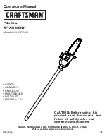
316.79246
Brand: Craftsman Pages: 20

TMSEm 2050
Brand: EM Pages: 140

ETS41
Brand: Elu Pages: 100

Sunjoe 24V-MPSWVG-LTE
Brand: SNOWJOE Pages: 20

93-800
Brand: ETC Tools Pages: 10

2220273
Brand: Kobalt Pages: 25


