background image


DOC ID - 1896 

• Rev 01 • DRAFT 00.08 

1 / 10 


ClareOne Wireless Security and Smart Home 
Panel Release Notes 

Content 

Introduction...1


Installing the panel...3


ClareOne setup...7


Known issues...10


Contact information...10


Last modified

: 03/10/20 

Introduction 

The ClareOne Wireless Security and Smart Home Panel (CLR-C1-PNL1) is a 
smart home hub featuring customizable home automation and security control. 
The ClareOne eliminates the need for separate control and customization 
devices.  

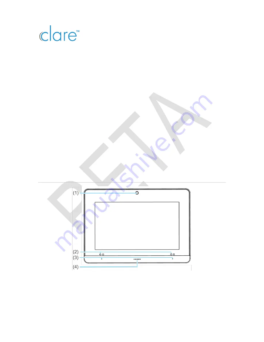
Figure 1: ClareOne Panel - front 


(1)  Camera 
(2)  IR sensors (2 on each side) 


(3) Microphones (on each side) 
(4) LED 

Summary of Contents for ClareOne CLR-C1-PNL1

Page 1: ...tact information 10 Last modified 03 10 20 Introduction The ClareOne Wireless Security and Smart Home Panel CLR C1 PNL1 is a smart home hub featuring customizable home automation and security control...

Page 2: ...screw 3 Rear panel cover 4 Mounting holes 5 Siren 6 DC routing hole 1 7 DC routing hole 2 8 LAN routing hole 9 Siren routing hole Figure 3 ClareOne Panel interior rear 1 DC wiring terminal 2 DC micro...

Page 3: ...The panel can be powered by the provided power supply with a micro USB cable using the provided power supply with Cat5 6 cable or using the provided power supply with 22AWG or thicker shielded securi...

Page 4: ...tabs are both fully pressed in 5 Press the sides of the back plate against the back of the panel making sure there is no gap between the back plate and the panel 6 Align the mounting holes in the bac...

Page 5: ...e panel 1 Select a location for the panel that is close to an outlet and then run a connection from the 12VDC supply to the selected installation location 2 Place the mounting bracket against the sele...

Page 6: ...the anchor locations and screw in one of the provided screws into each of the 4 hole locations 4 Remove the panel s back plate by pressing down on the 2 tabs and pulling the back plate outward exposin...

Page 7: ...utomatically powers up Note Do not connect to a receptacle controlled by a switch ClareOne setup Once the panel is installed in the desired location and is connected to a power source setup the ClareO...

Page 8: ...word and then tap Ok Note Tap to hide the keyboard 5 Add the desired sensors For full sensor configuration and management see ClareOne Wireless Security and Smart Home Panel User Manual DOC ID 1871 6...

Page 9: ...nue the wizard 8 Run any desired diagnostic tests and then tap Next Note Once installation is complete test the panel and sensors See ClareOne Wireless Security and Smart Home Panel User Manual DOC ID...

Page 10: ...ly 1628 Medium The Duress Code is renamable 1624 Medium C4 is unable to set the ClareOne panel to armed 1623 Medium C4 is not updated with trouble ClareOne panel trouble conditions 1706 Low Tapping th...

Reviews: