background image

Install the Chassis

Before you begin this task, ensure that you have read and understood the safety warnings in the Standard
Warning Statements section of the Safety Warnings handout topic.

Installing the Cisco NCS 5700 router involves these tasks:

The images in this chapter are only for representation purposes, unless specified otherwise. The chassis' actual
appearance and size may vary.

Note

Rack Types, on page 1

Rack Mount the Chassis, on page 2

Ground the Chassis, on page 35

Connect AC Power to the Chassis, on page 37

Connect DC Power to the Chassis , on page 40

Power Supply Unit Input and Output Ranges, on page 43
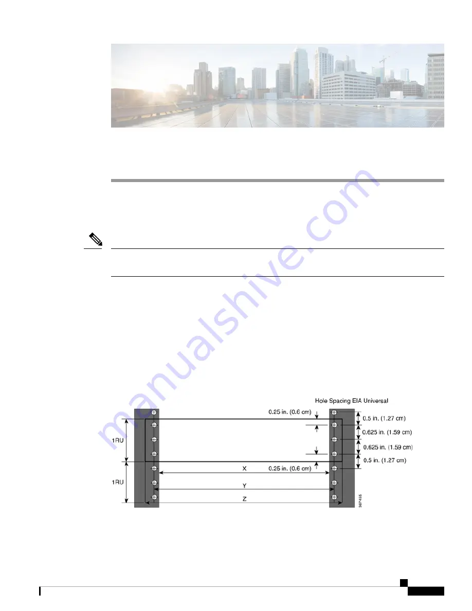
Rack Types

Figure 1: Rack specification EIA (19 inches and 23 inches)

Install the Chassis

1

Summary of Contents for NCS 5700

Page 1: ...images in this chapter are only for representation purposes unless specified otherwise The chassis actual appearance and size may vary Note Rack Types on page 1 Rack Mount the Chassis on page 2 Ground the Chassis on page 35 Connect AC Power to the Chassis on page 37 Connect DC Power to the Chassis on page 40 Power Supply Unit Input and Output Ranges on page 43 Rack Types Figure 1 Rack specificatio...

Page 2: ...mounted on a 2 post or a 4 post rack Rack Mount the NCS 57B1 Chassis in a 2 Post Rack on page 3 Contains the procedure for mounting the NCS 57B1 6D24 SYS and NCS 57B1 5DSE SYS chassis in a 2 post rack Rack Mount the NCS 57C1 Chassis in a 2 Post Rack with Sliders on page 5 Contains the procedure for mounting the NCS 57C1 chassis in a 2 post rack Rack Mount the NCS 57C3 MOD Chassis in a 2 Post Rack ...

Page 3: ...tion Quantity Rack mount brackets 2 M4 x 6 mm Phillips counter sink screws 8 Step 1 Install two rack mount brackets to the router as follows a Position the router so that its ports will be in the cold aisle b With the bracket ears aligned to the front of the chassis position a rack mount bracket on the side of the chassis so that the four holes are aligned to four of the screw holes on the side of...

Page 4: ...ets come in contact with two rack posts c Hold the chassis level while the second person inserts two screws 12 24 or 10 32 depending on the rack type in each of the two rack mount brackets using a total of four screws and into the cage nuts or threaded holes in the vertical rack mounting rails d Tighten the 10 32 screws to 20 in lb 2 26 N m or tighten the 12 24 screws to 30 in lb 3 39 N m Install ...

Page 5: ...ngaged or that the rack is otherwise stabilized Caution The following table lists the items contained in the rack mount kit provided with the routers Table 3 2 Post Rack Mount Kit Part Description Quantity Slider assembly left and right 2 Slider brackets left and right 2 12 24 Phillips pan head screws 10 M4 x 6 5 mm Phillips flat head screws 12 M4 x 8 mm Phillips pan head screws 2 Install the Chas...

Page 6: ...nstall the slider assembly on the rack as follows a Align the outer slider of the left slider assembly to the rear post rack holes and the inner slider of the left slider assembly to the front post rack holes The slider rail should be at the bottom b Use three 12 24 Phillips pan head screws two on the rear side and one on the front side with 30 in lb 3 39 N m to attach the slider assembly to the r...

Page 7: ...l 2 Slider assembly 1 Screws 3 In case of a 23 inch 2 post rack mount the slider assembly on the extension brackets following the same procedure outlined in Step 2 Note Install the Chassis 7 Install the Chassis Rack Mount the NCS 57C1 Chassis in a 2 Post Rack with Sliders ...

Page 8: ... the ports are in the cold aisle If the router has port side exhaust modules position the router so that the fan and power supply modules are in the cold aisle b With the slider bracket ears aligned to the front of the chassis as shown in the image use six M4x6 5mm flat head screws with 12 in lbs 1 4 N m to attach the bracket to the chassis c Repeat Steps 3b and 3c with the other slider bracket on...

Page 9: ...talled in the rack Slide the slider brackets onto the slider rails and then gently move the router all the way into the rack c Hold the chassis level while the second person inserts two pan head screws 12 24 in each of the two rack mount brackets using a total of four screws and into the cage nuts or threaded holes in the vertical rack mounting rails d Tighten the 12 24 screws to 30 in lb 3 39 N m...

Page 10: ...Figure 8 19 inch 2 Post Rack Mount Chassis Figure 9 23 inch 2 Post Rack Mount Chassis Install the Chassis 10 Install the Chassis Rack Mount the NCS 57C1 Chassis in a 2 Post Rack with Sliders ...

Page 11: ... Quantity Rack mount brackets 2 M4 x 6 mm Phillips counter sink screws 14 Step 1 Install two rack mount brackets to the router as follows a Position the router so that its ports will be in the cold aisle b With the bracket ears aligned to the front of the chassis position a rack mount bracket on the side of the chassis so that the seven holes are aligned to seven of the screw holes on the side of ...

Page 12: ...n contact with two rack posts c Hold the chassis level while the second person inserts six screws 12 24 or 10 32 depending on the rack type in each of the two rack mount brackets using a total of twelve screws and into the cage nuts or threaded holes in the vertical rack mounting rails d Tighten the 10 32 screws to 20 in lb 2 26 N m or tighten the 12 24 screws to 30 in lb 3 39 N m Install the Chas...

Page 13: ...at the rack is otherwise stabilized Caution The following table lists the items that are contained in the rack mount kit Table 5 NCS 57B1 6D24 SYS and NCS 57B1 5DSE SYS Router Rack Mount Kit Part Description Quantity Rack mount brackets 2 M4 x 6 mm Phillips flat head screws 18 M4 x 6 mm Phillips pan head screws 2 Rack mount guides 2 Rack mount slider rails 2 Grounding lug 1 Install the Chassis 13 ...

Page 14: ...hassis with its four holes that are aligned to four of the screw holes on the side of the chassis and then use four M4 counter sink screws to attach the bracket to the chassis Remove the grounding cover label and align the grounding cover plate with the grounding holes in the chassis and attach the rack mount brackets Note You can align four of the holes in the rack mount bracket to four of the sc...

Page 15: ...er rail before using a 12 24 screw Note b Repeat with the other slider rail on the other side of the rack c Use a tape measure and level to verify that the rails are at the same height and horizontal Step 4 Insert the router into the rack and attach it as follows a Holding the router with both hands position the back of the router between the front posts of the rack b Align the two rack mount guid...

Page 16: ...ngaged or that the rack is otherwise stabilized Caution The following table lists the items contained in the rack mount kit provided with the routers Table 6 4 Post Rack Mount Kit Part Description Quantity Slider assembly left and right 2 Slider brackets left and right 2 12 24 Phillips pan head screws 12 M4 x 6 5 mm Phillips flat head screws 12 M4 x 8 mm Phillips pan head screws 2 Install the Chas...

Page 17: ...nstall the slider assembly on the rack as follows a Align the outer slider of the left slider assembly to the rear post rack holes and the inner slider of the left slider assembly to the front post rack holes The slider rail should be at the bottom b Use four 12 24 Phillips pan head screws three on the rear side and one on the front side with 30 in lb 3 39 N m to attach the slider assembly to the ...

Page 18: ...l 2 Slider assembly 1 Screws 3 In case of a 23 inch 2 post rack mount the slider assembly on the extension brackets following the same procedure outlined in Step 2 Note Install the Chassis 18 Install the Chassis Rack Mount the NCS 57C1 Chassis in a 4 Post Rack with Sliders ...

Page 19: ...hat the ports are in the cold aisle If the router has port side exhaust modules position the router so that the fan and power supply modules are in the cold aisle b With the slider bracket ears aligned to the front of the chassis as shown in the image use six M4 flat head screws with 12 in lbs 1 4 N m to attach the bracket to the chassis c Repeat Steps 3b and 3c with the other slider bracket on th...

Page 20: ...alled in the rack Slide the slider brackets onto the slider rails and then gently move the router all the way into the rack c Hold the chassis level while the second person inserts two screws 12 24 in each of the two rack mount brackets using a total of four screws and into the cage nuts or threaded holes in the vertical rack mounting rails d Tighten the 12 24 screws pan head to 30 in lb 3 39 N m ...

Page 21: ...Figure 18 4 Post Rack Mount the NCS 57C1 Chassis Figure 19 23 inch 4 Post Rack Mount Chassis Install the Chassis 21 Install the Chassis Rack Mount the NCS 57C1 Chassis in a 4 Post Rack with Sliders ...

Page 22: ...tance can change The distance between the outside face of the front mounting rail and the outside face of the back mounting rail should be 16 0 to 19 9 inches 40 7to 50 5 cm to allow for rear bracket installation NC55 2RU ACC SL2 Designed for 19 inch min 650 x650 mm EIA cabinet standard 4 post rack This slider uses a tray PID NC57C3 ACC SL TR and the chassis is mounted to the tray Rack Requirement...

Page 23: ...he rack Note Figure 20 Slider Assembly Middle Slider Member 2 Outer Slider Member 1 Inner Slider Member 4 Unlock Feature on the Middle Slider Member 3 The following table lists the items that are contained in the Cisco NCS 57C3 MOD Router rack mount kit Table 7 Router Rack Mount Kit Part Description Quantity Rack mount brackets 2 Rack mount slider rails 2 M4 x 8 mm Phillips counter sink screws 8 M...

Page 24: ...for the NCS 57C3 MOD chassis 1 Step 1 Remove the inner slider member from the slider assembly by depressing the white tab present at the front of the slider assembly on the outer slider member Figure 21 Remove the Inner Slider Member from the Slider Assembly Blue Tab 2 White Tab 1 Step 2 Push the unlock feature of the middle slider member and slide the middle slider member back to the slider assem...

Page 25: ... Chassis M4 x 10 mm Phillips pan head screws 2 Inner slider member 1 For NC55 2RU ACC SL2 attach the inner slider member to the sides of the tray a Align the inner slider member with one side of the tray and use seven M4 x 8 mm flat head screws and tighten the screws to 12 in lbs 1 4 N m b Repeat this step to install the inner slider member to the other side of the tray Install the Chassis 25 Inst...

Page 26: ...he rack mount pins of the outer slider member do not fit the rack hole dimensions use the pins that are provided in the package Note b NC55 2RU ACC SL1 The front end of the outer slider member passes through the screw holes of the rack and latches to the rack See Figure 24 Rear and Front End NC55 2RU ACC SL1 of the Outer Slider Member Install the Chassis 26 Install the Chassis Rack Mount the NCS 5...

Page 27: ...ttach the slider to the front post with 2 counter sink screws 10 32 and washers See Figure 25 Rear and Front End NC55 2RU ACC SL2 of the Outer Slider Member Remove the screw thread adapter present at the front end of the outer slider member if you are unable to pass the slider through the rack holes Tighten the screws later after passing the slider through the rack holes Note Install the Chassis 2...

Page 28: ...nt End Outer slider member 1 Rear end Outer slider member 4 Washer 3 Rear end Rack mount pin 6 Front end Outer slider member 5 c Repeat 4a through 4b to install the outer slider member to the other side of the chassis Install the Chassis 28 Install the Chassis Rack Mount the NCS 57C3 MOD Chassis in a 4 Post Rack using Sliders ...

Page 29: ...ter Slider Member to the Rack Outer slider member 1 Step 5 Extend the middle slider member from the slider assembly Install the Chassis 29 Install the Chassis Rack Mount the NCS 57C3 MOD Chassis in a 4 Post Rack using Sliders ...

Page 30: ... slider members attached to the chassis or tray to the middle slider member on the rack Step 7 Slide the chassis or tray into middle slider member until it cannot be pushed further Install the Chassis 30 Install the Chassis Rack Mount the NCS 57C3 MOD Chassis in a 4 Post Rack using Sliders ...

Page 31: ... 2 Outer slider member 1 Inner slider member 3 Step 8 For NC55 2RU ACC SL2 with the tray do the following a Place the chassis on the tray and align the chassis with the screw holes on the tray Install the Chassis 31 Install the Chassis Rack Mount the NCS 57C3 MOD Chassis in a 4 Post Rack using Sliders ...

Page 32: ...ner slider member on both sides simultaneously to release the lock position Continue to push the chassis to the rack Step 10 Tighten the thumbscrews on either side of the chassis that is aligned with the screw thread adapter of the outer slider member through the rack holes Install the Chassis 32 Install the Chassis Rack Mount the NCS 57C3 MOD Chassis in a 4 Post Rack using Sliders ...

Page 33: ...Figure 31 Secure the Chassis to the Rack Figure 32 Secure the Tray to the Rack Install the Chassis 33 Install the Chassis Rack Mount the NCS 57C3 MOD Chassis in a 4 Post Rack using Sliders ...

Page 34: ...he chassis must be installed and secured to the rack Step 1 Remove the middle screws from either sides of the chassis Save the screws for re installation Step 2 Align the cable management bracket with the chassis as shown in the image Step 3 Tighten the 12 24 screws to 30 in lb 3 39 N m on either sides Install the Chassis 34 Install the Chassis Optional Install the Cable Management Bracket ...

Page 35: ...n a copper conductor wires must be used and the copper conductor must comply with NEC code for ampacity Caution When terminating the frame ground do not use soldering lug connectors screwless push in connectors quick connect connectors or other friction fit connectors Caution Step 1 Use a wire stripping tool to remove approximately 0 75 inches 19 mm of the covering from the end of the 6 AWG ground...

Page 36: ...Figure 33 NCS 57B1 6D24 SYS and NCS 57B1 5DSE SYS Ground Lug Figure 34 NCS 57C1 Ground Lug Chassis Rear Side Install the Chassis 36 Install the Chassis Ground the Chassis ...

Page 37: ...t interfere with other equipment Step 7 Prepare the other end of the grounding cable and connect it to an appropriate grounding point in your site to ensure adequate earth ground Connect AC Power to the Chassis The chassis relies on the protective devices in the building installation to protect against short circuit overcurrent and ground faults Ensure that the protective devices comply with local...

Page 38: ...S 1100W ACFW NCS 1100W ACFW port side intake airflow NCS 1100W ACRV NCS 1100W ACRV port side exhaust airflow In low line applications 90 140V AC redundancy is not guaranteed Therefore we recommend to use both AC power supplies Caution NCS 57C3 MOD S and NCS 57C3 MOD SE S To provide full output power of 1600 W the nominal voltage rating value ranges between 100 V to 240 V depending on the standards...

Page 39: ...Figure 36 Cable Clamp Examples Install the Chassis 39 Install the Chassis Connect AC Power to the Chassis ...

Page 40: ...nd national electrical codes Warning Before installing a DC power supply to the switch you will need to attach DC connection wires that you provide to the DC power connector included in the DC power supply s accessory kit For 240 380 VDC power supply the dual pole breaker or fuse rating is 20 A For 40 72 VDC power supply the single breaker or fuse is 40 A The following combinations of power suppli...

Page 41: ...nstructions Note Step 1 Verify that the correct fuse panel is installed in the top mounting space Step 2 Ensure that the DC circuit is powered down either breaker turned off or fuse pulled and proper lockout tag out procedures are followed Use the cable supplied with the power supply If you prefer to use your own cable the cable size must be 6 AWG Figure 38 NCS 57B1 Connecting DC Power Install the...

Page 42: ...t the DC connector into the DC receptacle on the power supply After the connection the black color DC negative wire appears on top To connect the PSU2KW DCPI power supply module with the power source you must procure the PWR 2KW DC CBL power cord Note To connect the NC57 1600W DCFW power supply module with the power source you must procure the CAB 48DC 40A 8AWG power cord Note Install the Chassis ...

Page 43: ...ions Table 8 Input and output power ranges for PSUs Output Output Power Input Current Max Input Voltage PID 12V 84A 1000W 12A 100 to 127V ac PSU2KW ACPI For low line applications 12V 167A 2000W 12A 200 to 240V ac PSU2KW ACPI For nominal voltage application 12V 167A 2000W 40A 40V to 72V DC PSU2KW DCPI 12V 90A 1100W 12A 100V to 240V ac NCS 1100W ACFW For port side intake For nominal voltage applicat...

Page 44: ...Install the Chassis 44 Install the Chassis Power Supply Unit Input and Output Ranges ...

Reviews: