background image

I

NSTALL THE

H

ARDWARE

C

ONNECT THE

RSP

S

TART AND

C

ONFIGURE THE

S

YSTEM

I

NSTALL

F

IELD

R

EPLACEABLE

U

NITS

(FRU

S

)

1

2

3

4

5

Quick Start Guide

Is Cisco documentation helpful? Click

here

 or go to http://www.cisco.com/warp/public/732/docsurvey/rtg/ to

give us your feedback.
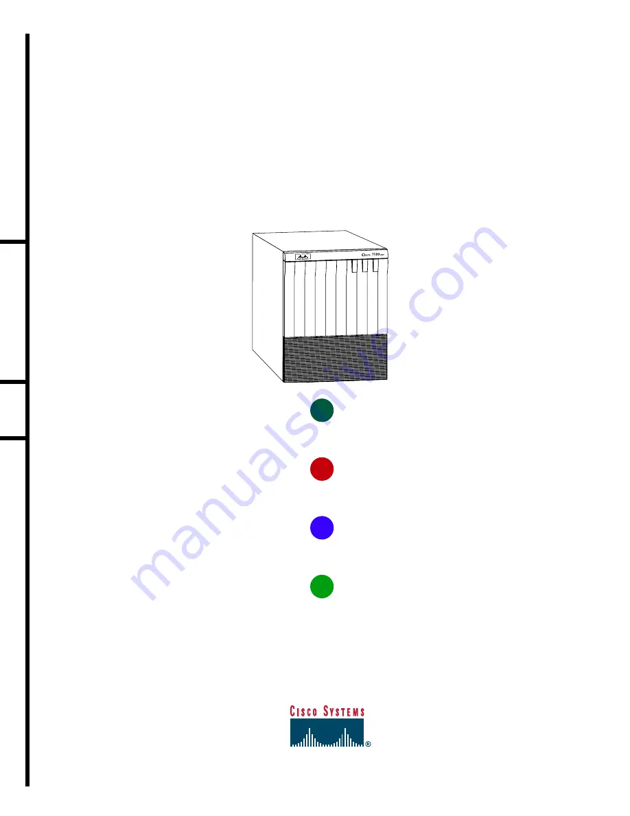
C

I S C O

7 5 0 7 R

O U T E R

57105

UPPER

POWER

LOWER

POWER

NORMAL 

Summary of Contents for 7507

Page 1: ...E THE SYSTEM INSTALL FIELD REPLACEABLE UNITS FRUS 1 2 3 4 5 Quick Start Guide Is Cisco documentation helpful Click here or go to http www cisco com warp public 732 docsurvey rtg to give us your feedback CISCO 7507 ROUTER 57105 UPPER POWER LOWER POWER NORMAL ...

Page 2: ......

Page 3: ...has seven slots slots 2 and 3 for the Route Switch Processors RSPs and slots 0 1 4 5 and 6 for the interface processors There are bays for up to two AC input or DC input power supplies One power supply is shipped as standard equipment a second power supply is optional A second optional power supply allows load sharing and increased system availability Packing List 1 Cisco 7507 router 1 Route Switc...

Page 4: ...with an attached spanner bar Two chassis ears each holds two captive grommets Fasteners Ten 10 32 x 5 8 inch LG Phillips pan head screws with integral washers Four M4 x 10 mm LG Phillips flat head screws Number 2 Phillips screwdriver One 7 16 inch open end or adjustable wrench if you will remove the chassis feet Tape measure or level both optional Ohmmeter if your installation requires the chassis...

Page 5: ... prevent injury Step 1 With a person positioned at either side of the chassis grasp the bottom edge of the chassis with one hand near the front and the other near the back Slowly lift the chassis in unison Place the chassis on a bench or tabletop where the air intake vent on the front of the chassis is not drawing in exhaust air from other equipment Step 2 Ensure that you have at least 3 or 4 feet...

Page 6: ...hillips pan head screws with integral square cone washers for mounting brackets and chassis ears to rack posts Chassis ear with captive sliding grommets Bracket To rack mount a Cisco 7507 router perform the following steps Step 1 Mount the brackets to the rack posts Step 2 Secure the spanner bars Step 3 Attach the chassis ears Step 4 Mount the chassis ...

Page 7: ... bracket with those in the rack post Step 3 Support the bracket with one hand and use the other hand to insert a 10 32 x 5 8 inch LG Phillips pan head screw through the bottom mounting hole on the front of the bracket and into the rack post Step 4 Secure the top of the bracket to the rack with two pan head screws Finger tighten the screws Step 5 Push the brackets as far apart as possible before us...

Page 8: ... spanner bar does not reach the opposite bracket loosen the pan head screws to allow more play between the brackets Step 4 Repeat Step 1 through Step 3 to fasten the remaining spanner bar to its anchor screw See C Step 5 Push the brackets as far apart as possible before tightening the screws Step 6 Use a Number 2 Phillips screwdriver to tighten the six pan head screws that secure the brackets to t...

Page 9: ...ar so that the mounting strips are flush with the end of the chassis and align the mounting holes in the ear with those in the chassis To center mount the chassis place each ear with the mounting strips away from the end of the chassis and align the mounting holes in the ear with those in the chassis Step 2 Use two M4 x 10 mm LG Phillips flat head screws to secure each ear to the chassis ...

Page 10: ...ep 1 Slowly lift the chassis in unison Lower it until it rests on the two ledges of the brackets Step 2 Slide the chassis back into the rack along the ledges Step 3 To remove a chassis foot use a 1 4 inch flat blade screwdriver or insert a 7 16 inch open end wrench between the underside of the chassis and the foot ...

Page 11: ... removing chassis foot H1396a Step 4 Turn the foot counterclockwise to loosen it until the foot drops out of the chassis Step 5 Continue sliding the chassis into the rack until the ears meet the front mounting posts on both sides of the rack Step 6 Secure each ear to the rack mounting post with two 10 32 x 5 8 inch LG Phillips pan head screws ...

Page 12: ...2 Place the interface processor filler VIP or RSP in the slot and align the guide on the carrier with the groove in the slot Step 3 Carefully slide the interface processor filler VIP or RSP into the slot until the faceplate makes contact with the ejector levers Step 4 Use the thumb and forefinger of each hand to push the ejector lever flat against the interface processor filler VIP or RSP Step 5 U...

Page 13: ...er supply to separate input lines the second power source will likely be available during a failure Step 1 For AC input power supplies confirm that the power on the power supply is off For DC input power supplies turn off the circuit breaker to which you will connect power and tape the breaker switch to the off position Step 2 Hold the power supply by the handle and place your other hand underneat...

Page 14: ...ower Supply section on page 13 to complete this procedure Step 6 Push the cable retention clip away from the power supply receptacle and push the power cable in until the cable retention clip snaps into place Step 7 Connect the opposite end of the power cable to an appropriate power source Step 8 Repeat Step 1 through Step 7 to install the second power supply optional ...

Page 15: ...OWER SUPPLY allation screws l block cover I O OUTFAIL INPUTPOWER DO NOT SHIP WITH POWER SUPPLY INSTALLED FASTENER TO BE FULLY ENGAGED BEFORE OPERATING POWER SUPPLY INPUT VOLTAGE 40 72 V INPUT CURRENT 24 13A NO SERVICEABLE COMPONENTS INSIDE Captive installation screws on terminal block cover B ...

Page 16: ...to L and negative to negative neutral to N The ground wire should always be connected first and disconnected last Step 4 Attach two nylon ties around the cable and the metal bracket for strain relief Step 5 Install the terminal block cover over the terminal block and tighten the captive installation screws Do not overtighten screws Step 6 Connect the opposite end of the DC input cable to the DC po...

Page 17: ...et up the terminal as follows 9600 baud 8 data bits no parity and 2 stop bits 9600 8N2 Connect the Auxiliary Port terminal DB 25 female DB 25 male RSP The auxiliary port on the RSP is an ETA TIA DTE DB 25 plug to which you can attach external equipment in order to access the router from the network The port is located next to the console port on the RSP and is labeled AUX Step 1 Connect the cable ...

Page 18: ...xiliary device Step 3 Repeat Step 2 for the other RSP or other external device H9720 CONSOLE CONSOLE DB 25 DB 25 sole terminal Console to cons RSPs in Step 1 Connect the DB 25 male end of the Y cable to the external auxiliary equipment Step 2 Connect one DB 25 female end of the Y cable to auxiliary ports on an RSP in an RSP slot Step 3 Repeat Step 2 for the auxiliary ports on a second RSP in an RS...

Page 19: ...interfaces go on and off in irregular sequence Step 6 Observe the LED indicators on the interface processors in your system When the system boot is complete a few seconds the RSP begins to initialize the interface processors During this initialization the indicators on each interface processor behave differently most flash on and off The enabled LED on each interface processor goes on when initial...

Page 20: ...nfiguration register value currently in effect The value is displayed on the last line of the screen display Configuration register is 0x141 will be 0x101 at next reload Step 7 Reboot the router and then perform a basic configuration using AutoInstall proceed to Step 8 Setup facility proceed to the Perform a Basic Configuration Using Setup section on page 19 Configuration mode proceed to the Perfo...

Page 21: ...password and the enable password when the following is displayed The enable secret is a one way cryptographic secret used instead of the enable password when it exists Enter enable secret barney The enable password is used when there is no enable secret and when using older software and some boot images Enter enable password betty Step 3 Enter yes or no to accept or refuse SNMP management Configur...

Page 22: ... IP yes yes Configure IGRP routing yes yes Your IGRP autonomous system number 1 15 Step 8 At the prompt enter the copy running config startup config command to save the configuration to NVRAM as follows Hostname copy running config startup config Note Consult your network administrator to obtain network addresses and subnet mask information ...

Page 23: ...tional zones that will be associated with your local zone Configure AppleTalk on this interface no yes Extended AppleTalk network no yes AppleTalk starting cable range 0 Step 4 At the prompt enter the copy running config startup config command to save the configuration to NVRAM as follows Hostname copy running config startup config Configure a Synchronous Serial Interface Step 1 Enter yes to confi...

Page 24: ...uter is now minimally configured and ready to use If you want to modify the parameters after the initial configuration use the setup command To perform more complex configurations use the configure command For more information on additional interface configuration and information on more specific system configurations refer to the Cisco 7500 Series Installation and Configuration Guide ...

Page 25: ... interface type slot port command at the enable prompt to enter interface configuration mode as follows Router config interface serial slot port Router config if Step 3 Press Ctrl Z to exit configuration mode Step 4 At the prompt enter the copy running config startup config command to save the configuration to NVRAM as follows Hostname copy running config startup config Your Cisco 7507 router is n...

Page 26: ...RUs A Flash memory card that ships with your Cisco 7507 contains the Cisco IOS software image to boot your router You do not need to format it 57002 SLOT 1 NORMAL SLOT 0 MASTER SLAVE SLOT 1 NORMAL SLOT 0 MASTER SLAVE A B C SLOT 1 NORMAL SLOT 0 MASTER SLAVE ...

Page 27: ...he card from the slot and place it in an antistatic bag to protect it Step 3 Face the front panel of the RSP and hold the Flash memory card with the connector end of the card toward the slot see A The label should face right Note The Flash memory card is keyed and cannot be seated the wrong way The eject button will not pop out if the card is not properly inserted Step 4 Insert the card into the a...

Page 28: ... copy the image file to Flash memory Upgrade images one at a time do not delete all known good images at one time You cannot copy an image while the system is running from Flash memory Use the command copy tftp filename bootflash slot0 slot1 filename for the copy procedure where tftp filename is the source of the file and bootflash slot0 slot1 filename is the destination in bootflash memory or on ...

Page 29: ...oads it will boot the image new image from the Flash memory card in slot 0 Router reload Enable Booting from Flash Memory To enable booting from Flash memory set configuration register bits 3 2 1 and 0 to a value between 2 and 15 in conjunction with the boot system flash device filename configuration command where device is bootflash slot0 or slot1 and filename is the name of the file from which y...

Page 30: ... HSA or high availability HA features provided you are using two RSPs Follow the instructions in the appropriate Route Switch Processor Installation and Configuration Guide such as the Route Switch Processor 8 RSP8 Installation and Configuration Guide Note The high system availability HSA and high availability HA features are beyond the scope of this Quick Start Guide For information on configurin...

Page 31: ...RSP but leave power on if you remove only the slave RSP Step 1 Attach an ESD preventive wrist strap between you and any unpainted chassis surface Step 2 If you have a VIP4 and are using HSA with an RSP2 as the slave processor remove the RSP2 and wait 20 30 seconds Step 3 Disconnect all cables from the interface processor VIP or RSP port adapters unless you are only moving a carrier then skip this ...

Page 32: ...processor go on and off in irregular sequence Step 3 Verify that the console terminal displays the system banner and startup screen as the system restarts Note Boot time is approximately 1 minute for systems with one RSP and approximately 1 5 minutes for systems with two RSPs Step 4 Verify that all the enabled LEDs on the interface processors are on Step 5 In systems with a second RSP installed an...

Page 33: ...cessor or VIP may not be fully seated in the backplane Refer to Appendix A in the Cisco 7500 Series Installation and Configuration Guide Step 3 If the VIP is new configure the new interfaces Enter the enable command at the EXEC prompt and then enter a privileged level password as follows Router enable Password Router Use the configure command to configure the interface processor or VIP Refer to th...

Page 34: ...d followed by the name or IP address of the remote server and then press Return to check the connection between the router and the remote host Step 3 Enter the show running config command to display the currently running configuration on the terminal and ensure that the configuration information is complete and correct If it is not use the configure command to add or modify the existing configurat...

Page 35: ...r the name or IP address of the remote host In the following example the name of the remote server is servername Router copy startup config tftp Remote host servername Translating servername domain server 1 1 1 1 OK ...

Page 36: ... confg ok The system displays a series of exclamation points or periods during the copy process The and ok indicate that the operation was successful A series of periods and timed out or failed indicates a failure of the process Install Field Replaceable Units FRUs If the display indicates that the process was successful the copy process is complete The configuration is stored on the remote file s...

Page 37: ...e default Router copy tftp startup config Step 4 Enter the IP address or name of the remote host the remote TFTP server to which you originally saved the configuration file Address of remote host 255 255 255 255 10 1 1 1 Step 5 Enter the name of the configuration file The default is to use the name of the router with the suffix confg Router confg in the following example If you specified a differe...

Page 38: ...ding steps If the process fails again contact your network administrator Install Field Replaceable Units FRUs Step 7 Enter the show startup config command to confirm that the configuration file was retrieved correctly Look at the first line for the configuration file size Compare it with the file you retrieved from the TFTP server to confirm that it is correct Following is an example Router show s...

Page 39: ...37 Remove and Install Port Adapters Install Field Replaceable Units FRUs Screw Upper edge Lower edge Carrier A B ...

Page 40: ...n the upper and the lower edges of the port adapter slot See B Step 4 Carefully slide the port adapter into the slot until the connector is completely seated in the connector at the rear of the port adapter slot as shown in B Step 5 Install the screw in the rear of the port adapter slot on the VIP Do not overtighten the screw See A Step 6 Carefully slide the VIP motherboard into the interface proc...

Page 41: ...and replacing it In this case proceed to Step 1 Step 1 Turn off the power source Step 2 Turn off the switch on the power supply Step 3 Disconnect the power cable from the power source Step 4 Disconnect the power cable from the power supply For the AC input power supply Lift up the cable retention clip and remove the power cable from the AC power receptacle Install Field Replaceable Units FRUs I O ...

Page 42: ...rt the bottom of the power supply OT SHIP WITH POWER SUPPLY ALLED FASTENER TO BE FULLY ENGAGED BEFORE OPERATING POWER SUPPLY INPUT VOLTAGE 40 72 V INPUT CURRENT 24 13A Captive installatio screw Power leads attac to terminal block negative positive ground H2530 Nylon ties on cab and metal bracke Warning Keep hands and fingers out of the power supply bays High voltage is present on the power backpla...

Page 43: ...ssible and Empowering the Internet Generation are service marks of Cisco Systems Inc and Aironet ASIST BPX Catalyst Cisco the Cisco Certified Internetwork Expert logo Cisco IOS the Cisco IOS logo Cisco Systems Cisco Systems Capital the Cisco Systems logo Enterprise Solver EtherChannel EtherSwitch FastHub FastSwitch IOS IP TV LightStream MICA Network Registrar PIX Post Routing Pre Routing Registrar...

Page 44: ...42 ...

Reviews: