


Chromalox
®
DIVISION
4
SECTION
TL
SALES
REFERENCE
DATE
SERVICE REFERENCE
Installation, Operation,
Maintenance Instructions
and
RENEWAL PARTS IDENTIFICATION
PD411-10
AUGUST, 2008
(Supersedes PD411-9)
161-048529-001
Incorporates PD410-8 and PD413-6.
These manuals have been discontinued.
Type TLC, TLO, TLS, TLI, KTLC, KTLO, KTLS,
KTLI, KBLC, KBLS, BLCK, & BLCS Series
Industrial Over-The-Side Immersion Heaters
© 2010 Chromalox, Inc.
Safety Guidelines
The safety and performance of this heater is dependent on proper
handling, installation, control and maintenance. As Chromalox can not
anticipate all conditions under which this information and heater, or
this heater in combination with other manufacturer’s products may be
used, it is advised that you conduct your own tests to determine the
safety and suitability of this heater in combination with other products
in your application. Where the consequences of overheating or failure
could result in personal injury or property damage, back-up controls
and safety devices are essential.
The Safety Alert Symbol: is found throughout these installa-
tion instructions to identify potential hazards that can result in person-
al injury. The seriousness of the potential risk is identified by one of
these three words:
– will result in serious injury or death.
– could result in serious injury or death.
– may result in minor or moderate injury.
Read and follow these instructions to minimize risks of electric
shock or fire. Save these instructions for future reference.
Chromalox Type TLC, TLO,TLS,TLI, KTLC, KTLO, KTLS,
KTLI, KBLC, KBLS, BLCK, & BLCS series industrial Over-The-
Side immersion heaters are designed for a wide variety of heating
applications.
1. Heater Construction Characteristics
A.
High quality resistance wire held in place by compacted
Magnesium Oxide Refractory or compacted proprietary
cement enclosed in a wide variety of sheath materials.
B.
Low to high watt densities.
C.
Standard selection of sheath materials include copper, steel,
INCOLOY
®
alloy and stainless steel. This broad selection of
sheath materials will operate successfully in many corrosive
solutions.
GENERAL
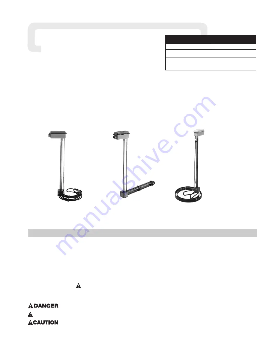
Type KTLC
Type TLC
Type KBLS
Shown above are Moisture Resistant Terminal Enclosures. Explosion Resistant Terminal Enclosure not shown.
Note:
Consult factory for specific installation instructions for heaters with additional features not detailed in this installation guide.
Such additional features may include thermocouples supplied as a special order modification.
!
!
WARNING


