ChlorKing NEXGEN80, Installation, Operation And Maintenance Manual
The ChlorKing NEXGEN80 is a reliable and efficient chlorine generator designed to keep your pool clean and sanitized. Ensure the proper installation, operation, and maintenance of this product by downloading the comprehensive "Installation, Operation And Maintenance Manual" for free at manualshive.com. Perfectly balanced for optimal performance, this manual is your essential resource for maximizing the benefits of your ChlorKing NEXGEN80.
Share
Download


Reviews:
No comments
Related manuals for NEXGEN80
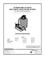
JSAL210F
Brand: Waterford Pages: 40

MONTAUK NB19836
Brand: Blue Wave Pages: 24

SMART-CLEAN
Brand: Nitro Pages: 16

DREAM POOL PROMO
Brand: GRE Pages: 44

Waterfun 3000005CH
Brand: Waterman Pages: 20

16/70
Brand: Dexton Pages: 20

PureWhite 2
Brand: J&J Electronics Pages: 2

GOBLIN CMARSSMRC-4Y
Brand: Calimar Pages: 10

OBLONG
Brand: GardiPool Pages: 8

P
Brand: Raypak Pages: 1

iCleaner-120
Brand: Hangzhou Gaoyue Technology Pages: 20

AMBASSADOR
Brand: ROUND Pools Pages: 40

HEAT-MAX RHS-5.5
Brand: HydroQuip Pages: 6

Bullet-1
Brand: AQUAMAXX Pages: 2

VITALIA
Brand: AQUALUX Pages: 2

Azores
Brand: GRE Pages: 24

Definition STR
Brand: JJ Pages: 103

TC 1655
Brand: Deltec Pages: 20


