Chino IR-FA Series, Instructions Manual
The Chino IR-FA Series, a cutting-edge product offering exceptional performance, now comes with a comprehensive Instructions Manual. This manual, available for free download on our website, provides users with easy-to-follow, step-by-step instructions to optimize their experiences with the Chino IR-FA Series.
Share
Download


Reviews:
No comments
Related manuals for IR-FA Series

COFIT EVO
Brand: Audio System Pages: 2

OmniPCX Office
Brand: Alcatel-Lucent Pages: 62

170.297
Brand: Skytec Pages: 12
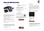
realpresence trio 8800
Brand: Polycom Pages: 7

Heat Control System
Brand: ORTAL Pages: 20

SDC 8000 DC
Brand: Sennheiser Pages: 1

TorqueTrak Revolution
Brand: Binsfeld Pages: 2

MERLIN LEGEND Release 2.0 Analog Multiline Telephone
Brand: AT&T Pages: 794

MSR 568 D3
Brand: Hyundai Pages: 88

ClearSound LoopHEAR 101
Brand: Geemarc Pages: 19

KH 2340
Brand: E-Bench Pages: 22

VTX
Brand: AMX Pages: 58

SA-AK770
Brand: Panasonic Pages: 24

SA-AK450GCP
Brand: Panasonic Pages: 8

SA-AK343P
Brand: Panasonic Pages: 26

SA-AK52
Brand: Panasonic Pages: 32

SA-AK340EE
Brand: Panasonic Pages: 26

SA-AK48
Brand: Panasonic Pages: 33


