background image

Part # MSP-DCCPPNR
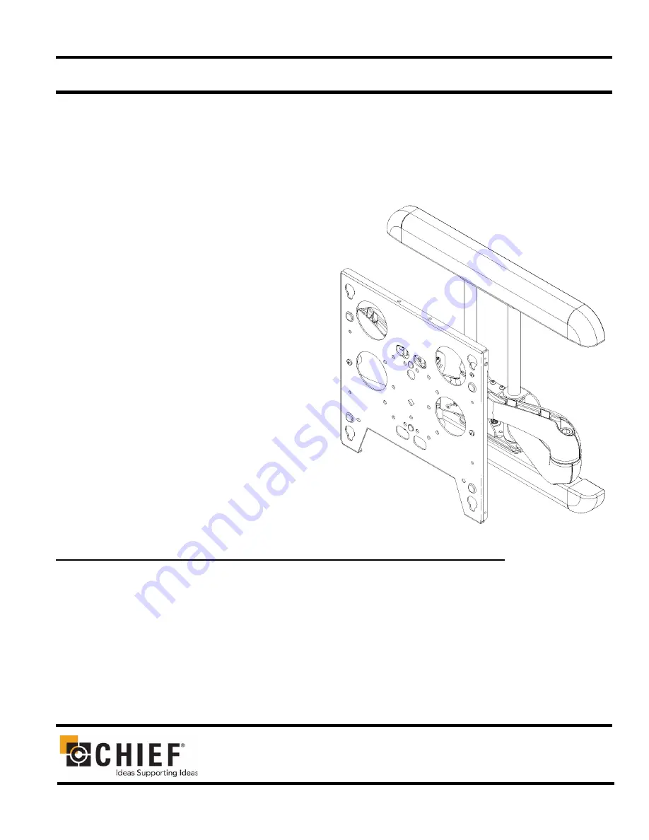
Large Flat Panel Dual Arm Wall Mount

The MSP-DCCPPNR is wall-mounted, rugged, versa-
tile, and installer-friendly. The mount is compatible 
with the standard (14” x 14”) PSB interface bracket in 
which a display can be mounted in either the land-
scape or portrait position on the mount.

The dual arms on the MSP-DCCPPNR:

Extend from the wall 24-7/8” in length

Pivot up to 90º left or right of center

The standard mount is shipped with the support posts 
for the dual arms centered in the mount. The support 
posts can be moved laterally right or left of center to 
readily accommodate sites with limited wall space. 
The mount also has two inches of height adjustment. 
The tilt range for the display is 5º up and 15º down.

The MSP-DCCPPNR was designed for fast installa-
tion. After drawing the plumb line and installing the 
two top lag bolts into the dual wall studs, the installer 
hangs the mount on its top bracket and installs two lag 
bolts in the bottom bracket. Next, the installer makes 
the height adjustment, mounts the display, and con-
nects the power/audio/video cables, which are 
diverted into the built-in path in the swing-out arms. 
After making the lateral, rotational, and tilt adjust-
ments, the installation process is complete.

BEFORE YOU BEGIN                                                                         

Caution:  To prevent damage to the PNR, which could affect or void the Factory warranty, and to the equip-
ment that will be attached to it, thoroughly study all instructions and illustrations before you begin the 
installation.  Pay particular attention to the “Important Warnings and Cautions” on Page 2.

The combined weight of the components installed on the PNR must not exceed 200 lbs. (90.72kg).

The PNR wall mount must be installed on dual wall studs or supporting framework. The wall to which the PNR is 
anchored must be capable of supporting 

five times

 the total weight of the mount and all attached equipment.

If a defect is discovered after Dell’s initial 21 day Customer Satisfaction period, Chief Mfg. will, at its option, repair 
or replace the product at no charge provided it is returned during the warranty period.  Please note contact informa-
tion for Chief Mfg. listed below:

CHIEF MANUFACTURING INC.

1-800-582-6480

  952-894-6280  FAX 952-894-6918

8401 EAGLE CREEK PARKWAY, STE. 700
SAVAGE, MINNESOTA 55378  USA

PART NO. 8805-000146  (Rev. B)

2005 Chief Manufacturing

www.chiefmfg.com

10/05

I N S T A L L A T I O N   I N S T R U C T I O N S

Summary of Contents for MSP-DCCPPNR

Page 1: ...verted into the built in path in the swing out arms After making the lateral rotational and tilt adjust ments the installation process is complete BEFORE YOU BEGIN Caution To prevent damage to the PNR which could affect or void the Factory warranty and to the equip ment that will be attached to it thoroughly study all instructions and illustrations before you begin the installation Pay particular ...

Page 2: ...mount must not exceed 200 lbs 90 72kg the maximum load capacity of the mount WARNING Watch for pinch points Do not put your fingers between movable parts WARNING Make sure the mount and brackets are correctly oriented WARNING Make sure the flag securing the display is completely lowered at all times except when removing or installing the display CAUTION Check the unit for shipping damage before yo...

Page 3: ...3 Installation Instructions MSP DCCPPNR DIMENSIONAL DRAWING ...

Page 4: ...lude the PSB interface bracket INTERFACES Table 2 on page 4 provides the applicable mount interfaces TOOLS REQUIRED FOR INSTALLATION Allen wrench set Drill and bit set Wrench set NOTE Other tools may be required depending on the method of installation PARTS LIST Unpack the carton and verify the contents listed in Table 3 on page 4 If you are missing any of the listed parts contact Customer Service...

Page 5: ...r supporting framework that is vertical or horizontal 2 Using a stud sensor locate the two wood studs where you will install the mount 3 Draw a level plumb line to indicate the desired height of the top mounting bracket 4 With an assistant lift and hold the mount against wall Use a pencil awl or small nail to mark the mounting holes where two pilot holes will be drilled into the cen ter of the woo...

Page 6: ...t b Slide the mount into the desired position on the wall and tighten the two lag bolts 2 Mount the bottom bracket on the mount as follows a Mark the two mounting holes in the bottom mounting bracket see Figure 3 Make sure to align the holes parallel to the holes drilled in the top bracket b Drill two pilot holes in the wall studs c Install two lag bolts and two washers into the pilot holes d Tigh...

Page 7: ...ght do the following Turn adjustment nut see Figure 4 clockwise CW to lower the unit height or Turn adjustment nut counterclockwise CCW to raise the unit height Install Cover Plates and End Caps NOTE The cover plates and end caps have pressure fitting ends that lock in place with each other 1 Install cover plate 20 over the top bracket See Figure 5 2 Install end cap 30 on the cover plate 20 See Fi...

Page 8: ... mount Make sure buttons of PSB interface bracket fully engage all teardrop slots of the mount 4 Secure the mounting bracket to the mount by completely engaging the locking device see Figure 6 WARNING Make sure the locking device securing the dis play is completely engaged at all times except when removing or installing the display The locking device must be completely engaged during installation ...

Page 9: ... video cables along bottom arm see Figure 8 using tiewraps 50 not shown to secure cables to each arm and through cable channel CAUTION To prevent equipment damage do not route cables through holes in the display mounting plate 3 Route power audio video cables to an open area behind the mounting plate not shown Leave a sufficient amount of slack in cables to allow for connection and extension where...

Page 10: ...nt components 1 Using a 9 16 wrench slightly tighten or loosen lateral tilt tension adjustment nut see Figure 10 2 Mount the display and check for desired tilt tension 3 Repeat Steps 1 and 2 until desired tilt tension is obtained Rotational Tilt Tension Adjustment 1 If necessary loosen or tighten bottom rotational tilt tension adjustment nut see Figure 11 2 Mount the display and check for desired ...

Page 11: ... inch to the right of center Reconfiguring the Swing Arms Left of Center With some disassembly and re assembly required you can move the swing arms to the left of center by reconfiguring the mount Use the first and third slotted holes in the top and bottom mounting brackets Reconfiguring the Swing Arms Right of Center With some disassembly and re assembly you can move the swing arms to the right o...

Page 12: ...er see Figure 14 4 Install retaining pin assemblies one top and one bottom and secure using two bolts one top and one bottom 5 Install four bolts two on the top and two on the bottom to secure the swing arm assembly to the top and bottom mounting brackets see Figure 14 6 Tighten the bolts 7 Install the display on the mount REMOVE THE DISPLAY Perform this procedure when maintenance is required WARN...

Page 13: ... repositioned in order to gain access to the tension adjustment screw s 3 Using the wrench provided with the mount turn adjust ment bar clockwise to increase swing arm tension or coun terclockwise to reduce swing arm tension see figure 16 and see figure 17 NOTE Small adjustments of 1 8 turn or less are typically all that is required to achieve desired tension 4 Check swing arm tension If desired t...

Page 14: ......

Reviews: