background image


9828093379 ed 00 05/2020 1 


INSTRUCTION AND MAINTENANCE MANUAL 


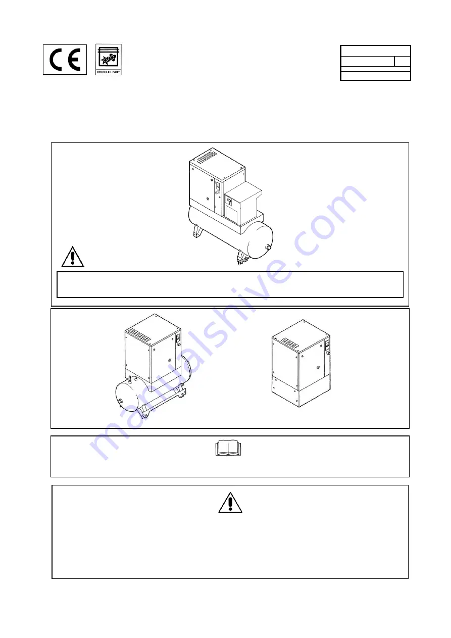
SILENCED SCREW ROTARY COMPRESSOR UNITS 


HP 3 - 4 - 5,5 - 7,5 - 10 

KW 2,2 - 3 - 4 - 5,5 - 7,5


Code 

9828093379  00 


Edition 05/2020 


READ THIS MANUAL CAREFULLY BEFORE CARRYING OUT ANY OPERATIONS ON THE COMPRESSOR 
UNIT. 


THIS MACHINE MUST BE CONNECTED TO TWO DIFFERENT POWER SUPPLIES: THREE-PHASE OR SINGLE-
PHASE SUPPLY FOR THE COMPRESSOR AND SINGLE-PHASE SUPPLY FOR THE DRYER


THIS MACHINE IS DESIGNED FOR BOTH CONTINUOUS AND INTERMITTENT WORKING, 

HOWEVER TO AVOID CONDENSATION PROBLEMS IN THE OIL, THE MACHINE MUST OPERATE 

CONTINUOUSLY IN LOAD FOR AT LEAST 10% OF THE TIME, CHECK FOR SIGNS OF 

CONDENSATION IN THE OIL BY FOLLOWING THE INSTRUCTIONS GIVEN IN CHAPTER 15.2


Summary of Contents for HP 10

Page 1: ...OR UNIT THIS MACHINE MUST BE CONNECTED TO TWO DIFFERENT POWER SUPPLIES THREE PHASE OR SINGLE PHASE SUPPLY FOR THE COMPRESSOR AND SINGLE PHASE SUPPLY FOR THE DRYER THIS MACHINE IS DESIGNED FOR BOTH CONTINUOUS AND INTERMITTENT WORKING HOWEVER TO AVOID CONDENSATION PROBLEMS IN THE OIL THE MACHINE MUST OPERATE CONTINUOUSLY IN LOAD FOR AT LEAST 10 OF THE TIME CHECK FOR SIGNS OF CONDENSATION IN THE OIL ...

Page 2: ... THE UNIT 18 0 LIST OF SPARE PARTS FOR ROUTINE MAINTENANCE 19 0 TROUBLE SHOOTING AND EMERGENCY REMEDIES PART B INFORMATION RESERVED FOR TECHNICALLY SKILLED PERSONNEL 20 0 STARTING UP 21 0 GENERAL ORDINARY MAINTENANCE REQUIRES TRAINED PERSONNEL 22 0 CHANGING THE OIL 23 0 CHANGING THE OIL SEPARATING FILTER 24 0 BELT TENSION 25 0 REPLACING THE BELT 26 0 FLOW DIAGRAM 27 0 CALIBRATIONS FOR DRYER WIRING...

Page 3: ...HESE POLLUTING AND HAZARDOUS PRODUCTS MUST COMPULSORY BE DISPOSED BY CHARGING AUTHORISED AND SPECIALISED FIRMS ACCORDING TO THE DIFFERENT TYPOLOGY OF PRODUCT DIFFERENTIATE THE COMPRESSOR COMPONENTS ACCORDING TO THE DIFFERENT CONSTRUCTION MATERIALS PLASTIC COPPER IRON OIL FILTER AIR FILTER ETC The manufacturer does not accept responsibility for damage caused as a result of negligence or failure to ...

Page 4: ...rier and is then dried and sent to the distribution network Dryer operation is described below The gaseous refrigerant coming from the evaporator 4 is sucked by the refrigeration compressor 1 and it is pumped into the condenser 2 This one allows its condensation eventually with the help of the fan 3 the condensed refrigerant passes through the dewatering filter 8 and it expands through the capilla...

Page 5: ... VOLTAGE 7 HOT PARTS 3 AIR NOT FIT FOR BREATHING 8 MOVING PARTS 4 NOISE 9 FAN ROTATING 5 MACHINE WITH AUTOMATIC START 10 PURGE EVERY DAY 5 1 DESCRIPTION OF COMPULSORY SIGNALS 11 READ THE USE AND MAINTENANCE INSTRUCTIONS 6 0 DANGERS ZONES 6 1 DANGERS ZONES FOR COMPRESSOR UNIT FIG 3 Risks present on the whole machine FIG 3 2 2 8 9 2 1 ...

Page 6: ...n the whole machine 7 0 SAFETY DEVICES 7 1 SAFETY DEVICES FOR SCREW COMPRESSOR FIG 5 1 Safety screws 2 The front protection can be opened with a special key 3 Fixed protection device cooling fan pulley 4 Safety valve 5 Emergency stop 6 Oil filling cap with safety breather FIG 4 6 2 6 9 3 2 2 1 6 1 3 3 2 ...

Page 7: ...093379 ed 00 05 2020 7 7 2 SAFETY DEVICES FOR DRYER UNIT AND TANK FIG 6 1 Safety valve 2 Protective switch cap 3 Relay for compressor automatic 4 Overload protector for compressor 4 6 FIG 5 5 1 2 1 3 1 2 1 FIG 6 2 3 4 1 ...

Page 8: ... purposes and must not be removed or spoiled for any reason 1 Dangers plate Code 2202 2607 90 2 Plate Machine with automatic start Code 2202 2510 89 8 2 POSITION OF THE DANGER PLATES FOR DRYER UNIT AND TANK FIG 8 The plates fitted on the compressor unit are part of the machine they have been applied for safety purposes and must not be removed or spoiled for any reason 1 Dangers plate 1079 9926 55 ...

Page 9: ...ENGLISH Code 9828093379 ed 00 05 2020 9 8 3 POSITION OF THE DATA PLATE FOR COMPRESSOR UNIT FIG 9 FIG 9 3 6 1 6 2 6 2 1 4 5 2 1 4 3 1 2 5 6 ...

Page 10: ...g the room temperature must not be higher than 46 C or lower than 5 C The volume of the room must be about 30 m3 The room must be provided with 2 openings for ventilation with a surface area of about 0 5 m2 each The first opening must be in a high position to evacuate the hot air the second opening must be low to allow the intake of external air for ventilation If the environment is dusty it is ad...

Page 11: ...re no visibly damaged parts If you are in doubt do not use the machine but apply to the manufacturer technical assistance service or to your dealer The packing material plastic bags polystyrene foam nails screws wood metal strapping etc must not be left within the reach of children or abandoned in the environment as they are a potential source of danger and pollution Dispose of these materials in ...

Page 12: ...nd single phase Check the condition of the line leads and ensure that there is an efficient earth lead Ensure that there is an automatic cut out device upstream for the machine against overcurrents with a differential device see Ref 1 for compresseur Ref 2 for dryer wiring diagram Connect the machine power cables with the greatest care according to the standards in force These cables must be as in...

Page 13: ...NG TO THE PRESCRIPTIONS OF THE REGULATIONS IN FORCE IN THE COUNTRY OF USE ALL DAMAGE DUE TO THE FAILURE TO COMPLY WITH THESE INDICATIONS CANNOT BE ATTRIBUTED TO THE MANUFACTURER AND MAY CAUSE INVALIDITY OF THE GUARANTEE CONDITIONS The manual drainage Ref 2 Fig 14 the condensate automatic Ref 3 Fig 14 are led outside the machine with a flexible pipe that may be inspected Drainage must comply with t...

Page 14: ...ard unit IEC V400 3 50Hz PED CE approval The weight may vary according to the voltage variant and approval of the pressure equipment Weight air receiver 270L add 35kg 77lb Weight air receiver 500L add 60kg 133lb HP kW Dryer type Weight Kg lb Freon R 513A Kg lb Nominal power W HP Nominal power W HP Nominal power W HP bar psi MAX 230 50Hz 230 60Hz 115 60Hz 230 50Hz 230 60Hz 115 60Hz 230 50Hz 230 60H...

Page 15: ...r 2 Condenser 3 Motor fan 4 Evaporator 5 Condensate drain solenoid valve 6 Hot gas bypass valve 7 Refrigerant filter 8 Expansion capillary tube 9 Safety valve Compressed air tank 10 Compressed air tank 11 Condensate manual drainage IT IS FORBIDDEN TO TAMPER WITH THE SETTING VALUES OF THE SAFETY VALVE 10 9 10 11 1 2 3 4 5 6 7 8 FIG 15 11 ...

Page 16: ... tightening system 7 Minimum pressure valve 8 Air oil separator filter 9 Top up or oil filling cap 10 Control panel 11 Oil gauge 12 Oil discharge 13 Oil tank 14 Pressure sensor Base Controller 15 Safety valve 16 Electric motor 17 Screw compressor 18 Suction unit 19 Oil cooler IT IS FORBIDDEN TO TAMPER WITH THE SETTING VALUES OF THE SAFETY VALVE 5 5 kW 4 1ph 60Hz machines are equipped with unloader...

Page 17: ...LIVE HP 3 4 5 5 kW 2 2 3 4 STARTING Move the selector Ref 2 to position ON Move the selector Ref 5 to position I the selector will return automatically The compressor starts running operation lamp Ref 4 lights up STOPPING Move the selector Ref 5 to position 0 Lamp Ref 4 goes out Move the selector Ref 2 to position OFF HP 7 5 10 kW 5 5 7 5 and HP 5 5 kW 4 for 1ph 60Hz STARTING Move the selector Ref...

Page 18: ... 7 5 10 HP and 4 kW 5 5 HP single phase 60Hz machines the controller maintains the net pressure between programmable limits by automatically loading and unloading the compressor A number of programmable settings e g the unloading and loading pressures the minimum stop time and the maximum number of motor starts are taken into account The controller stops the compressor whenever possible to reduce ...

Page 19: ...s the compressor to start stop with an external switch signal Only your dealer can do the activation Please contact him for further details Controller 14 4 2 DETAILED DESCRIPTION Reference Designation Function 1 Display Shows icons and operating conditions 2 LED Voltage on Indicates that the voltage is switched on 3 Start stop button Keep pressed for 3 seconds to start compressor Press to stop com...

Page 20: ...e Automatic restart after voltage failure is active Active protection functions Emergency stop Service Service required Units Pressure unit Mega Pascal Pressure unit pounds per square inch Pressure unit bar Temperature unit degree Centigrade Temperature unit degree Fahrenheit Motor A time delay parameter is displayed NOTE x1000 ON if the displayed value is in thousands of hrs ON if the displayed v...

Page 21: ...r 14 4 5 MAIN FUNCTION Toswitchonthe compressor press start stop button 3 for 3seconds The compressor starts andthe status isshown Screen with running compressor Tostopthecompressor push start stopbutton 3 The compressor immediately unloads for 5 5 7 5 kW 7 5 10HP unitsand 4kW 5 5HP single phase unit or stops 3 4kW 4 5 5HP units Screen with unloading compressor When the unload time is elapsed only...

Page 22: ...oll in the menu with the up or down buttons 4 8 To select one item push the enter button 7 To end the current action push start stop 3 button If the emergency stop button is pushed the compressor stops immediately and the following screen will appear Emergency stop When the emergency push button is restored reset the alarm by pressing the enter button 7 for 5 seconds The following screen will appe...

Page 23: ...atus of other parameters by pressing the enter button 7 for 3 seconds Press button 3 to stop the compressor and wait until the compressor has stopped The warning message will disappear as soon as the warning condition disappears 14 4 7 SHUTDOWN DESCRIPTION THE COMPRESSOR WILL SHUTDOWN In case the temperature at the outlet of the compressor element exceeds the shutdown level detected by temperature...

Page 24: ...ar Main screen with shutdown indication element outlet temperature The related pictograph will appear flashing Scroll Up or Down buttons 4 8 until the current element outlet temperature appears Shutdown screen element outlet temperature The screen shows that the temperature at the outlet of the compressor element is 117 C When the shutdown condition has been solved press the Enter button 7 for 5 s...

Page 25: ...OTOR OVERLOAD In the event of motor overload The compressor will shut down or the compressor can t start Alarm LED 5 will flash The following screen will appear Main screen with shutdown indication motor overload Contact you dealer for fault troubleshooting When the shutdown condition has been solved press the enter button 7 for 5 seconds When rSt appears on the display the compressor can be resta...

Page 26: ...mer has reached the preset time interval If the service timer exceeds the programmed time interval alarm LED 6 is blinking with a following screen Blinking screen Press Enter button 7 to enter the main menu Select dAtA and press Enter button 7 to enter the data menu Scroll buttons 4 8 until d 6 appear the service symbol is shown Press enter button 7 The actual reading of the service timer is shown...

Page 27: ...verview of the menu From the Main screen press the enter button 7 for 3 seconds to enter the Menu You will find the following items Data menu Data counters parameters Programming menu Submenu of Regulation pressure Timer Display setting and Control setting Test menu Display test Info menu Information of firmware release ...

Page 28: ...e band settings uPr 2 Calling up modifying pressure band settings tiMr Timer SrV d Calling up maintenance warning diSP Display tEMP Calling up modifying unit of temperature PrES Calling up modifying unit of pressure bC LG Calling up modifying time of backlight Ctrl Control Lo rE Local remote start stop Ar Af Calling up automatic restart after voltage failure Ar d Delay automatic restart after volt...

Page 29: ...n 7 for 3 seconds to enter the Main menu Select dAtA and press Enter button 7 to enter the Data menu Scroll Up or Down buttons 4 8 until d 2 and the motor symbol is shown Press Enter button 7 the number of motor starts is shown This screen shows the number of motor starts x1 or if x1000 lights up x1 000 In the above example the number of motor starts is 10100 14 4 12 CALLING UP MODULE HOURS Starti...

Page 30: ...ed hrs or x1000 hrs and the value 1755 the compressor has been running loaded for 1755 hours 14 4 14 CALLING UP LOAD SOLENOID VALVE ONLY FOR 5 5 7 5KW UNITS Starting from the Main screen Press Enter button 7 for 3 seconds to enter the Main menu Select dAtA and press Enter button 7 to enter the Data menu Scroll Up or Down buttons 4 8 until d 5 and the running loaded symbol is shown Press Enter butt...

Page 31: ...ecompressor has run 1191 hours since the previous service To reset the timer contact your supplier 14 4 16 CALLING UP MODIFYING PRESSURE BAND SELECTION Starting from the Main screen Press Enter button 7 for 3 seconds to enter the Main menu Select ProG and press Enter button 7 to enter the Programming menu Scroll Up or Down buttons 4 8 to reG P for regulation pressure Press Enter button 7 to enter ...

Page 32: ...e C and F Scroll Up or Down buttons 4 8 to set the unit of temperature and press Enter button 7 to confirm The unit blinks and is saved 14 4 19 CALLING UP MODIFYING THE UNIT OF PRESSURE The unit of pressure measurement can only be changed when the compressor is stopped Starting from the Main screen Press Enter button 7 for 3 seconds to enter the Main menu Select ProG and press Enter button 7 to en...

Page 33: ...compressor will wait for a fixed time When delay time is running the display will show the related countdown value as below Example countdown delay time of automatic restart after power failure 14 4 22 KEYBOARD LOCK Keep both Up and Down buttons pressed for more than 3 seconds to lock or unlock the keyboard The display will show the label Loc blinking for 3 seconds if the keyboard has been locked ...

Page 34: ...OOD KNOWLEDGE OF THE COMMAND FUNCTIONS 1 Digital controller 2 Alarms 3 Power ON 4 Fan ON 5 Dryer ON 6 PDP indicator 7 Stop Running button ICON MODE FUNCTIONS ALARM OFF No active alarms ON Probe failure alarm High Low temperature alarm COMPRESSOR OFF Dryer off FLASH Maintenance warning ON Dryer on FAN OFF Fan off FLASH n a ON Fan on 1 5 4 3 2 6 1 7 ...

Page 35: ...probe failed replace probe Warning icon NOT fashing label H2 flashing High PDP call for service refrigerant leak flow rate inlet temperature exeeding the limit Warning icon NOT fashing label L2 flashing Low PDP call for service hot gas by pass valve out of order ambient temperature lower then limits EE ALARM EE alarm is shown when internal EPROM errors happens if this warning will appear the dryer...

Page 36: ...rm 2 Push and hold buttons SET and DOWN to enter in the menu 3 Message SE appears on display 4 Push and release button UP 5 Message rS appears on display 6 Push and release button SET 7 Message n appears on display 8 Push and release button UP 9 Message y appears on display 10 Push and release SET to reset service alarm 11 Message y blinks for 3 seconds 12 Then rL is fixed and C blinks on display ...

Page 37: ... on display 4 Push and release SET to enter in the SE menu 5 Current service interal is displayed 60 or different value from 0 to 99 6 Select desired service interval using UP or DOWN 40 4000h 55 5500h 80 8000h 7 Push and release SET to configure new service interval 8 Value selected blinks for 3 seconds 9 Then rS is fixed and C blinks on display for 10 seconds New service interval is set UP DOWN ...

Page 38: ... Contact your supplier if in doubt Every Day after use Drain the condensate from the air tank Check the automatic drainage of the condensate dryer Every 50 working hours or at least weekly Drain condensate from the oil tank Check the oil level Clean the filtering panel Every 500 hours or at least every 3 months Clean the air suction filter Clean the condenser battery on the dryer if fitted Clean t...

Page 39: ...NG THE CONDENSATE IT IS OBLIGATORY TO STOP THE MACHINE AND DISCONNECT IT FROM THE POWER MAINS Proceed as follows Switch off the machine with pushbutton Ref 1 Fig 18 Press the button switch Rif 2 Fig 18 on the dryer if fitted Disconnect the power supply by means of the disconnector switch Ref 3 on the screw compressor and Ref 4 on the dryer if fitted Fig 18 Wait for the machine to cool down Remove ...

Page 40: ... MACHINE DO NOT MIX DIFFERENT TYPES OF OIL BEFORE CARRYING OUT ANY OPERATION ON THE MACHINE ENSURE THAT THE ELECTRIC POWER SUPPLY HAS BEEN DISCONNECTED Open the front protection Ref 5 Fig 18 using the special key Remove the fixed protection device machine cover Ref 9 Fig 18 Slowly unscrew the oil cap Ref 8 Fig 18 ensuring there is no pressure inside Top up to maximum level Ref 7 Fig 18 with oil of...

Page 41: ...EANING THE FILTERING PANEL Stop the machine Turn on the differential supply switch Rif 3 Fig 20 Clean the filtering panel Rif 1 Fig 19 with a jet of air wash it with water do not use solvents FIG 19 1 EVERY 50 WORKING HOURS CLEAN THE FILTERING PANEL ...

Page 42: ... the cover Ref 6 Fig 20 Check the direction of the arrow Remove the filter Ref 7 Fig 20 AVOID DROPPING FOREIGN BODIES INTO THE SUCTION MANIFOLD Clean the filter with a jet of air working from inside to outside DO NOT USE WATER OR SOLVENTS Alternatively fit a new filter Clean the disk on which the filter rests with a clean cloth Fit the filter and the cover If necessary dispose of the old filter in...

Page 43: ...d as follows Stop the compressor Switch off the dryer by pressing the STOP button Ref 2 Fig 21 Open disconnect the differential supply switch Ref 3 on the screw compressor and Ref 4 on the dryer if fitted Fig 21 HOT PARTS INSIDE Remove the cover panel Ref 5 Fig 21 Clean the condenser fins Ref 6 Fig 21 with compressed air DO NOT USE WATER OR SOLVENTS Close the cover panel Ref 5 Fig 21 15 8 CLEAN TH...

Page 44: ...e in the unit is all released One day after stop there may be some condensate in the bottom of the oil tank Drain this condensate During periods of inactivity the unit must be protected against atmospheric agents dust and humidity which could damage the motor and the electrical system For stops above 2 weeks it s recommended to install VCI foam in the cubicle and canopy To restart the machine afte...

Page 45: ...PTION Code HP 3 4 5 5 kW 2 2 3 4 HP 7 5 10 kW 5 5 7 5 8 10 bar 8 10 bar 1 Suction air filter 6211 4737 50 1 Suction air filter 6211 4739 50 2 Oil filter 6211 4726 50 3 Separator cartridge 6221 3726 50 3 Separator cartridge 6221 3728 50 4 Filtering panel version on floor base frame 2202 2607 00 FIG 23 2 3 1 4 ...

Page 46: ...ect 2B the main motor protection device has tripped 2C Temperature switch on element outlet has tripped Verify phase sequence to check possible motor failure environment temperature too high improve ventilation in the compressor room Chapter 9 2 cooling radiator is dirty clean the radiator oil level too low top up the oil tank 3 The machine does not start The red LED Ref 5 Fig 17 A is flashes The ...

Page 47: ...rking under bad conditions of condensation Check the solenoid exhaust valve Check the drainage timer Check the flow rate of treated air Check the room temperature Check the air temperature at the drier inlet Clean the condenser Check the good operation of the fan 3 The compressor head is very hot 55 C Make reference to 2B Make reference to 2C 3A The cooling circuit is not working with the right ga...

Page 48: ...HAS BEEN DISCONNECTED 20 1 PREPARING FOR SETTING UP FIG 24 After checking everything as indicated in Chap 12 folow the instructions in Fig 24 Fit the sound absorbing panels Ref 1 Fig 24 These parts are packed in the bodywork THIS PART B OF THE INSTRUCTIONS MANUAL IS RESERVED FOR PROFESSIONALLY SKILLED PERSONNEL AUTHORISED BY THE MANUFACTURER FIG 24 1 1 ...

Page 49: ...f 4 Fig 25 Remove the air filter Ref 5 Fig 25 Pour a little oil into the suction unit Reassemble the air filter Ref 5 Fig 25 Reassemble the cover Ref 4 Fig 25 If more than 6 months have passed between the inspection in the factory and the date of installation consul the manufacturer 20 3 STARTING THE DRYER FIG 25 Start the dryer before turning on the compressed air The compressed air piping will b...

Page 50: ...ation is correct the paper sheet Ref 3 is blown up See Fig A If the rotation is not correct the paper sheet remains flat See Fig B PHASE INCORRECT ALL WORK ON THE ELECTRIC PLANT HOWEVER SLIGHT MUST BE CARRIED OUT BY PROFESSIONALLY SKILLED PERSONNEL Disconnect the energy supply and invert two connections as per Ref 1 Fig B IT IS ADVISABLE NOT TO DO ANYTHING ON THE MACHINE PANEL IF ALL THE INSTRUCTI...

Page 51: ...ensate dryer Every 50 working hours or at least weekly Drain condensate from the oil tank Check the oil level Clean the filtering panel Every 500 hours or at least every 3 months Clean the air suction filter Clean the condenser battery on the dryer if fitted Clean the filter of the automatic condensate drain Check belt tension Every 2000 hours or at least every 1 year Change the suction filter Cha...

Page 52: ... 1 Close all the protections cover and front protection Ref 3 Fig 27 Start the compressor After about 1 minute stop the machine PROCEED AS DESCRIBED AT CHAPTER 15 3 THE OLD OIL MUST BE DISPOSED OF IN COMPLIANCE WITH THE REGULATIONS IN FORCE NOTE ON LUBRICANTS When delivered the machine is filled with oil In normal conditions of use these lubricants have proved to be able to withstand use for as ma...

Page 53: ...ve the fixeds protections device Ref 2 3 4 Fig 29 Loose the screws by half a turn Ref 5 Fig 29 Adjust the belt tension by turning the screws Ref 6 Fig 29 Close the screws again Ref 5 Fig 29 The belt tensioning values are indicated with a label on the element motor frame The force and deflection varies with the power of the unit and with the total running hours of the belt Close the fixeds protecti...

Page 54: ...ENGLISH 54 Code 9828093379 ed 00 05 2020 FIG 29 5 5 6 2X f F 4 3 2 1 3 2 1 4 6 2X 5 9 5 Tightening torque 25 N m HP 3 4 5 5 7 5 10 kW 2 2 3 4 5 5 7 5 7 8 ...

Page 55: ...CH EP 5 AIR OIL RECEIVER TEMPERATURE SENSOR BC 6 OIL FILTER 16 DRIVE MOTOR 7 THERMOSTATIC VALVE 17 SOLENOID VALVE 8 OIL COOLER 18 SIGHT OIL LEVEL 9 PRESSURE SWITCH EP 19 VALVE PURGE AIR RECEIVER PRESSURE SENSOR BC 20 NON RETURN VALVE AND NOZZLE 10 PRESSURE GAUGE EP 21 NON RETURN VALVE 7 5 10 HP 5 5 7 5 kW COMPRESSOR CONTROLLER BC 22 NOZZLE 7 5 10 HP 5 5 7 5 kW EP ELECTRO PNEUMATIC VARIANT BC BASE ...

Page 56: ...RESSURES AND TEMPERATURES OF R513A SUCTION SIDE OF REFRIGERATION COMPRESSOR Evaporating Temp C Evaporating Pressure bar RATED VALUES Temp 20 C 1 2 R513A 2 35 2 47 27 1 FLOW DIAGRAM OF THE DRYER 1 REFRIGERANT COMPRESSOR 2 GAS CONDENSER 3 FAN MOTOR 4 HEAT EXCHANGER 5 DEMISTER CONDENSATE SEPARATOR 6 IMPURITY TRAP 7 CAPILLARY TUBE 8 REFRIGERATION FLUID FILTER 9 HOT GAS BYPASS VALVE 10 AIR TO AIR EXCHA...

Reviews: