background image


CHEETAH Hardware User’s Manual 


Imperx, Inc. 


Rev. 1.6 

6421 Congress Ave.  


8/26/2016 

Boca Raton, FL 33487 
+1 (561) 989-0006    

1 of 121 


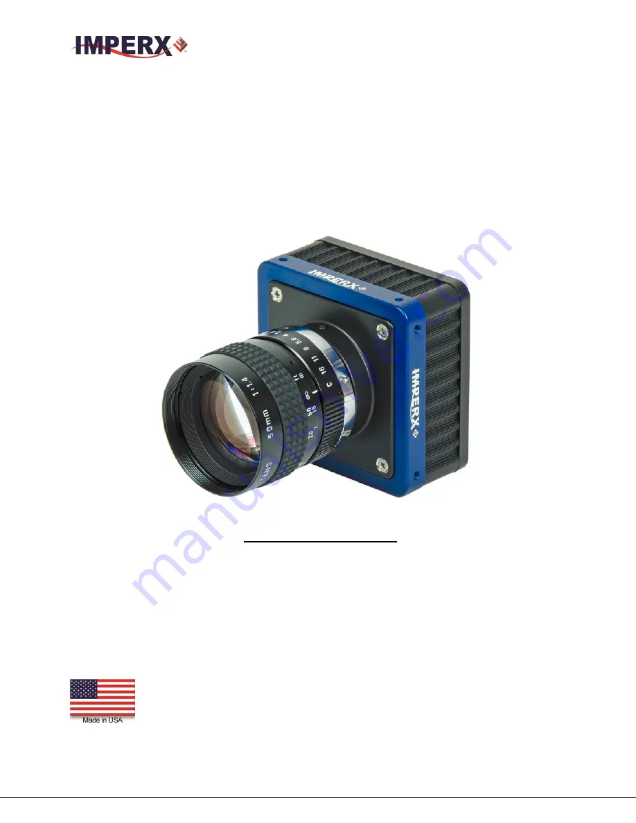
CHEETAH C5180, C4181, C4180 and C3880 Hardware 

User’s Manual 


HIGH-SPEED, HIGH-RESOLUTION, AND VERSATILE CMOS DIGITAL 

CAMERAS 


CONFIDENTIAL NOTICE: 


These  products  are  not  intended  for  use  in  life  support  appliances,  devices,  or  systems  where  malfunction  of  these 
products can reasonably be expected to result in personal injury. Imperx customers using or selling these products for 
use  in  such  applications  do  so  at  their  own  risk  and  agree  to  fully  indemnify  Imperx  for  any  damages  resulting  from 
such improper use or sale. 
 
Copyright © 2011, Imperx Inc. All rights reserved. All information provided in this manual is believed to be accurate 
and reliable. Imperx assumes no responsibility for its use. Imperx reserves the right to make changes to this information 
without notice. Redistribution of this  manual in  whole or in part, by any  means, is prohibited  without obtaining prior 
permission from Imperx. 


Summary of Contents for C3880

Page 1: ...expected to result in personal injury Imperx customers using or selling these products for use in such applications do so at their own risk and agree to fully indemnify Imperx for any damages resulting from such improper use or sale Copyright 2011 Imperx Inc All rights reserved All information provided in this manual is believed to be accurate and reliable Imperx assumes no responsibility for its ...

Page 2: ...6 K Wetzel Updated minimum ROI width to 320 Rev 1 4 5 25 16 K Wetzel Update Figure 51 description removed single tap mode from Figures 15 16 and 17 Zero ROT not supported in Averaging mode Rev 1 5 6 7 16 K Wetzel Updated PG period and width in Section 2 9 Rev 1 6 7 22 16 K Wetzel Updated Mechanical Drawings in 1 6 4 Cheetah images and Appendix E Power Supply Schematic Rev 1 7 8 19 2016 M Pangburn ...

Page 3: ...CL Output 19 1 5 2 Camera Link Full Signal Mapping 20 1 5 3 Camera Link Physical Layer to Camera Link Receiver Bits 22 1 5 4 Camera Link Bit to Port Bit assignments 23 1 5 5 Camera Link Port assignments based on selected output configuration 27 1 5 6 Camera Power Connector 28 1 6 MECHANICAL OPTICAL and ENVIRONMENTAL 29 1 6 1 Mechanical 29 1 6 2 Optical 29 1 6 3 Environmental 30 1 6 4 Mechanical Dr...

Page 4: ... 43 2 7 2 Digital Gain 44 2 7 3 Digital Offset 44 2 7 4 Black Level Auto calibration and Black Level Offset 44 2 8 DATA OUTPUT FORMAT 44 2 8 1 Bit Depth 44 2 8 2 Output Taps 45 2 9 PULSE GENERATOR 45 2 10 I O CONTROL 46 2 10 1 Input Output Mapping 46 2 10 2 Electrical Connectivity 46 2 11 TEST IMAGE PATTERNS 48 2 11 1Test Image patterns 48 2 12 WHITE BALANCE AND COLOR CONVERSION 49 2 12 1 White Ba...

Page 5: ...64 3 3 5 Frame Exposure Control 66 3 3 6 Exposure Time Internal 66 3 3 7 Programmable Frame Period Enable 67 3 3 8 Output Pixel Clock Rate and Zero ROT 67 3 3 9 Fixed Frame Period 67 3 3 10 Area of Interest 68 3 3 11 Decimation Averaging or Subsampling 68 3 3 12 Black Level auto calibration 69 3 3 13 Analog and Digital Gain 69 3 3 14 Triggering Workspace Registers 70 3 3 15 Strobe Control Register...

Page 6: ...d Output Mapping 95 4 7 5 Data Output Panel 97 4 7 6 Color 100 CHAPTER 5 CHEETAH WARRANTY AND SUPPORT 101 5 1 ORDERING INFORMATION 102 5 2 TECHNICAL SUPPORT 102 5 3 WARRANTY 103 APPENDIX A CAMERA CONFIGURATION REFERENCE 104 A 0 ABBREVIATIONS 105 A 1 SAVING AND RESTORING REGISTERS 105 A 2 CAMERA INFORMATION REGISTERS 105 A 3 ACQUISITION REGISTERS Stored in FLASH 106 A 4 TRIGGER REGISTERS 107 A 5 PU...

Page 7: ...DEX OF TABLES Table 1 Cheetah C5180 C4181 C4180 and C3880 Overview 11 Table 2 Cheetah General Features List 17 Table 3 Cheetah C5180 C4181 C4180 C3880 Specifications 19 Table 4 CLF Camera Output Connector 1 Signal Mapping 21 Table 5 CLF Camera Output Connector 2 Signal Mapping 22 Table 6 Camera Link Connector 1 X0 X3 24 Table 7 Camera Link Connector 2 Y0 Y3 25 Table 8 Camera Link Connector 2 Z0 Z3...

Page 8: ...re 7 CLF Camera output connector 2 21 Figure 8 Camera Link bit sequence over the physical connection 23 Figure 9 Camera Power Connector Viewed from rear 28 Figure 10 C5180 C4181 C4180 and C3880 Mechanical Drawings 31 Figure 11 Global Shutter with 8 33mS exposure time 33 Figure 12 Horizontal and vertical window positioning 37 Figure 13 Monochrome pixel averaging 39 Figure 14 Monochrome sub sampling...

Page 9: ... View Menu 86 Figure 39 Help menu 87 Figure 40 About CamConfig 88 Figure 41 Acquisition Control Panel 89 Figure 42 Exposure control window 90 Figure 43 AOI Functions 91 Figure 44 Subsampling Functions 91 Figure 45 Video Amp parameter Menu 92 Figure 46 Trigger parameter Menu 93 Figure 47 Pulse Generator Panel 94 Figure 48 Strobe Control Panel 96 Figure 49 Data Output Panel 97 Figure 50 DPC and HPC ...

Page 10: ... Manual Imperx Inc Rev 1 7 6421 Congress Ave 8 26 2016 Boca Raton FL 33487 1 561 989 0006 10 of 121 Chapter 1 Introduction Introduction This chapter outlines the key features of the CHEETAH C5180 C4181 C4180 and C3880 cameras ...

Page 11: ...3 ONSEMI NOIP1SN012KA CLF CXP C3880M 3840 x 2896 75 Mono 4 3 ONSEMI NOIP1SN010KA CLF CXP C3880C 3840 x 2896 75 Color 4 3 ONSEMI NOIP1SN010KA CLF CXP Table 1 Cheetah C5180 C4181 C4180 and C3880 Overview 1 1 GENERAL DESCRIPTION The CHEETAH cameras are advanced intelligent high resolution progressive scan fully programmable and field upgradeable CMOS cameras They are built around On Semiconductors ar...

Page 12: ...t for pixels that are over responding or under responding Auto White Balance AWB is available in color cameras to correct for color temperature The cameras have a Camera Link interface that includes 8 10 12 bits data transmission with two four eight or ten output taps as well as camera control all on one or two cables The cameras are fully programmable via the Camera Link interface The adaptabilit...

Page 13: ...ernal inputs one opto isolated and two external outputs one opto isolated Flat Field Correction FFC User and Factory Camera Link Base Medium Full and Deca support Temperature monitor Field upgradeable firmware LUT DPC HPC FFC 1 3 CHEETAH SPECIFICATIONS 1 3 1 General Information A CMOS camera is an electronic device for converting light into an electrical signal The camera contains a light sensitiv...

Page 14: ...columns respectively into an array of 64 A D converters The camera takes care of all the details of re ordering the lines within frame grabber memory Unlike a CCD where digitization is performed within one pixel time these cameras perform digitize at 1 64th the pixel rate 64 A D converters and the digitization has a depth of 10 bits The image sensor provides up to thirty two LVDS outputs and the t...

Page 15: ...erx Inc Rev 1 7 6421 Congress Ave 8 26 2016 Boca Raton FL 33487 1 561 989 0006 15 of 121 Figure 2 shows a typical CMOS image sensor architecture Figures 3 and 4 show the camera s spectral response Figure 2 CMOS image sensor architecture ...

Page 16: ... Ave 8 26 2016 Boca Raton FL 33487 1 561 989 0006 16 of 121 1 3 2 Spectral Sensitivity Curves Figure 3 Python CMOS mono spectral response Monochrome with the cover glass Figure 4 Python CMOS typical color spectral response Color with Microlens and with cover glass ...

Page 17: ...Global only Exposure time 4 s min Area of Interest one Analog Gain Up to 10dB Digital Gain Up to 24dB Subsampling Keep one skip one Pixel Averaging mono 1x2 2x1 and 2x2 Auto White Balance Yes Test Image Static Dynamic Defective pixel correction Static Dynamic User DPM Hot pixel correction Static Dynamic User HPM Inputs 1 LVTTL 1 Opto coupled Outputs 1 5v TTL 1 Opto coupled Triggers Programmable Ri...

Page 18: ...10 bit 32 fps 8 bit 40 fps 10 bit 50 fps 8 bit Dynamic Range 59 dB 59 dB Shutter speed 4 s to 1 sec 4 s to 1 sec Area of Interest One One Analog gain 0 to 10dB 8 10 bit 0 to 10dB 8 10 bit Digital gain 0 to 24dB 0 to 24dB Black level offset 0 to 1024 1 step 0 to 1024 1 step User LUT 2 LUTs Gamma User LUT 2 LUTs Gamma User LUT Hardware trigger Asynchronous Asynchronous Strobe Modes Programmable Widt...

Page 19: ...Ts Gamma User LUT 2 LUTs Gamma User LUT Hardware trigger Asynchronous Asynchronous Strobe Modes Programmable Width Delay Programmable Width Delay Trigger Sources External Pulse Generator Computer External Pulse Generator Computer Trigger features Rising Falling edge De glitch Delay Strobe Rising Falling edge De glitch Delay Strobe Size W x H x L CLB 72 0 x 72 0 x 39 8 mm 72 0 x 72 0 x 39 8 mm Weig...

Page 20: ...ink Full Signal Mapping Camera data output is compliant with Deca 80 bit Full 64 bit Medium 48 bit and Base 24 bit Camera Link standard up to 80 data bits 4 sync signals LVAL FVAL DVAL and User Out 1 reference clock 2 external inputs CC1 CC2 and a bi directional serial interface The camera link output connectors are shown in Figure 6 and 7 and the corresponding bit and port mapping is described be...

Page 21: ... 18 X CLK LVDS Out Camera Link Clock Tx PAIR 5 6 X 3 LVDS Out Camera Link Channel Tx PAIR 5 19 X 3 LVDS Out Camera Link Channel Tx PAIR 6 7 SerTC LVDS In Serial Data Receiver PAIR 6 20 SerTC LVDS In Serial Data Receiver PAIR 7 8 SerTFG LVDS Out Serial Data Transmitter PAIR 7 21 SerTFG LVDS Out Serial Data Transmitter PAIR 8 9 CC 1 LVDS In User Selectable Input PAIR 8 22 CC 1 LVDS In User Selectabl...

Page 22: ... 8 9 Z 1 LVDS Out Camera Link Channel Tx PAIR 8 22 Z 1 LVDS Out Camera Link Channel Tx PAIR 9 10 Z 2 LVDS Out Camera Link Channel Tx PAIR 9 23 Z 2 LVDS Out Camera Link Channel Tx PAIR 10 11 Z CLK LVDS Out Camera Link Clock Tx PAIR 10 24 Z CLK LVDS Out Camera Link Clock Tx PAIR 11 12 Z 3 LVDS Out Camera Link Channel Tx PAIR 11 25 Z 3 LVDS Out Camera Link Channel Tx Base Wire 13 Power Return Ground ...

Page 23: ...nk bit sequence over the physical connection 1 5 4 Camera Link Bit to Port Bit assignments Tables 6 8 describe how the Camera Link Receiver bits received from X0 X3 Y0 Y3 and Z0 Z3 physical connections on CL connectors 1 and are translated into the Camera Link Port bits based on the selected Camera Link Configuration Base Medium Full or Deca ...

Page 24: ... Deca 0 A0 A0 A0 1 A1 A1 A1 2 A2 A2 A2 3 A3 A3 A3 4 A4 A4 A4 5 A7 A5 A7 6 A5 A6 A5 7 B0 A7 B0 8 B1 B0 B1 9 B2 B1 B2 10 B6 B2 B6 11 B7 B3 B7 12 B3 B4 B3 13 B4 B5 B4 14 B5 B6 B5 15 C0 B7 C0 16 C6 C0 C6 17 C7 C1 C7 18 C1 C2 C1 19 C2 C3 C2 20 C3 C4 C3 21 C4 C5 C4 22 C5 C6 C5 23 SPR C7 I1 24 LVAL LVAL LVAL 25 FVAL FVAL FVAL 26 DVAL D0 I0 27 A6 D1 A6 Table 6 Camera Link Connector 1 X0 X3 ...

Page 25: ...ca Deca 0 D0 D2 D0 1 D1 D3 D1 2 D2 D4 D2 3 D3 D5 D3 4 D4 D6 D4 5 D7 D7 D7 6 D5 E0 D5 7 E0 E1 E0 8 E1 E2 E1 9 E2 E3 E2 10 E6 E4 E6 11 E7 E5 E7 12 E3 E6 E3 13 E4 E7 E4 14 E5 F0 E5 15 F0 F1 F0 16 F6 F2 F6 17 F7 F3 F7 18 F1 F4 F1 19 F2 F5 F2 20 F3 F6 F3 21 F4 F7 F4 22 F5 G0 F5 23 SPR G1 I4 24 LVAL G2 LVAL 25 FVAL G3 I2 26 DVAL G4 I3 27 D6 LVAL D6 Table 7 Camera Link Connector 2 Y0 Y3 ...

Page 26: ...8tap10bit Deca Deca 0 G0 G5 G0 1 G1 G6 G1 2 G2 G7 G2 3 G3 H0 G3 4 G4 H1 G4 5 G7 H2 G7 6 G5 H3 G5 7 H0 H4 H0 8 H1 H5 H1 9 H2 H6 H2 10 H6 H7 H6 11 H7 I0 H7 12 H3 I1 H3 13 H4 I2 H4 14 H5 I3 H5 15 I4 I5 16 I5 J3 17 I6 J4 18 I7 I6 19 J0 I7 20 J1 J0 21 J2 J1 22 J3 J2 23 SPR J4 J7 24 LVAL J5 LVAL 25 FVAL J6 J5 26 DVAL J7 J6 27 G6 LVAL G6 Table 8 Camera Link Connector 2 Z0 Z3 ...

Page 27: ...5 a4 a3 a2 a1 a0 f7 f6 f5 f4 f3 f2 f1 f0 e7 e6 e5 e4 e3 e2 e1 e0 d7 d6 d5 d4 d3 d2 d1 d0 MODE C7 C6 C5 C4 C3 C2 C1 C0 B7 B6 B5 B4 B3 B2 B1 B0 A7 A6 A5 A4 A3 A2 A1 A0 4x8 D7 D6 D5 D4 D3 D2 D1 D0 B7 B6 B5 B4 B3 B2 B1 B0 B9 B8 A9 A8 A7 A6 A5 A4 A3 A2 A1 A0 4x10 D9 D8 C9 C8 C7 C6 C5 C4 C3 C2 C1 C0 D7 D6 D5 D4 D3 D2 D1 D0 B7 B6 B5 B4 B3 B2 B1 B0 B11 B10 B9 B8 A11 A10 A9 A8 A7 A6 A5 A4 A3 A2 A1 A0 4x12 ...

Page 28: ...H2 H1 H0 G7 G6 G5 G4 G3 G2 G1 G0 J7 J6 J5 J4 J3 J2 J1 J0 C9 C8 C7 C6 C5 C4 C3 C2 B9 B8 B7 B6 B5 B4 B3 B2 A9 A8 A7 A6 A5 A4 A3 A2 8x10 F9 F8 F7 F6 F5 F4 F3 F2 E9 E8 E7 E6 E5 E4 E3 E2 D9 D8 D7 D6 D5 D4 D3 D2 D1 D0 C1 C0 B1 B0 A1 A0 H9 H8 H7 H6 H5 H4 H3 H2 G9 G8 G7 G6 G5 G4 G3 G2 H1 H0 G1 G0 F1 F0 E1 E0 Table 12 Image data bit to port assignments Deca modes 1 5 6 Camera Power Connector The male 12 pi...

Page 29: ...amera Power Connector Pin Mapping 1 6 MECHANICAL OPTICAL and ENVIRONMENTAL 1 6 1 Mechanical The camera housing is manufactured using high quality zinc aluminum alloy and anodized aluminum For maximum flexibility the camera has eight 8 M3X0 5mm mounting screws located towards the front and the back An additional plate with 20 UNC tripod mount and hardware is shipped with each camera All dimensions ...

Page 30: ...ondensing Always keep the camera as cool as possible Always allow sufficient time for temperature equalization if the camera was kept below 00 C The camera should be stored in a dry environment with the temperature ranging from 500 to 900 C CAUTION NOTE 1 Avoid direct exposure to moisture and liquids The camera housing is not hermetically sealed and any exposure to liquids may damage the camera el...

Page 31: ...anual Imperx Inc Rev 1 7 6421 Congress Ave 8 26 2016 Boca Raton FL 33487 1 561 989 0006 31 of 121 1 6 4 Mechanical Drawings 1 6 4 1 C5180 C4181 C4180 and C3880 Drawings Figure 10 C5180 C4181 C4180 and C3880 Mechanical Drawings ...

Page 32: ...dware User s Manual Imperx Inc Rev 1 7 6421 Congress Ave 8 26 2016 Boca Raton FL 33487 1 561 989 0006 32 of 121 Chapter 2 Camera Features Camera Features This chapter discusses the camera s features and their use ...

Page 33: ... the array begins In this way all pixels capture the image during the same time period reducing any image artifacts due to motion within the scene The maximum exposure is frame time dependent and the minimum exposure is 4 microseconds The camera normally overlaps the exposure and readout times as shown in Figure Figure 11 Figure 11 Global Shutter with 8 33mS exposure time 2 1 2 External exposure c...

Page 34: ...sing or skipping data In this way the dark current generated within the pixel and the dark current noise is minimized 2 2 1 2 Programmable Frame Time Control Once the Pixel Clock has been adjusted to minimize the line readout time the user can increase the frame time by using the Programmable Frame Time feature When programmable frame time control is enabled the frame is readout and then the camer...

Page 35: ...e total the interface bandwidth The output interface clock speed for the Cheetah Camera is 85 MHz Camera Link Spec is 85 MHz maximum It is important to match the camera s output to the frame grabber Select a frame grabber or camera output based upon the following criteria of data rate CLF C5180 Camera Bit Depth Output Data Rate Gbit s Full Resolution Imperx VCE CLPCIe04 fps Full Resolution Frame R...

Page 36: ...e 17 C3880 frame rates vs output taps 2 3 AREA OF INTEREST 2 3 1 Overview For some applications the user may not need the entire image but only a portion of it To accommodate this requirement CHEETAH provides one Region of Interest ROI also known as Area of Interest AOI The camera offers a pre programmed quad full HD QFD AOI 3840 x 2160 resolution to simplify camera setup for QFHD applications The...

Page 37: ...2 Horizontal and vertical window positioning Note Color version users when AOI is enabled for proper color reconstruction and WB Offset X and Offset Y must be an even number 2 3 3 Factors Impacting Frame Rate The camera frame rate depends upon a number of variables including the exposure time number of rows and columns in the AOI the amount of decimation within the image and the bandwidth of the o...

Page 38: ...ase 2 taps selected and with 10 bit digitization and 10 bit output mode selected the frame rate is limited by the output interface bandwidth of 2 04 Gbps 2 3 3 1 AOI Frame Rate Examples The Tables below describe resulting frame rate FR for various AOIs using Camera Link Deca output The frame grabber speed will impact results and values below assume an x8 speed frame grabber The camera will calcula...

Page 39: ...esolution by averaging several pixels together and has the advantage of reducing aliasing and reducing noise increasing SNR Subsampling however increases output frame rate more than pixel averaging It is not possible to apply both averaging and sub sampling decimation simultaneously Zero ROT is not supported when averaging is enabled Color cameras do not support pixel averaging The graphic below i...

Page 40: ...he output frame size but maintains the full field of view If an area of interest AOI is selected then the field of view of the AOI is maintained The C5180 C4181 C4180 and C2880 employ a keep one pixel skip one pixel sequence When enabled in both x and y every other pixel within a line is retained and every other line within the image is retained C4181 Figure 14 Monochrome sub sampling Figure 15 Co...

Page 41: ...a built in programmable pulse generator refer to Pulse Generator section In Internal triggering mode the camera receives the trigger signal from the internal pulse generator Software the camera expects a single trigger one clock cycle generated by the computer The user can trigger the camera by depressing the GUI Trigger button or by writing any data to address 0x6030 2 5 2 Acquisition and Exposur...

Page 42: ...rigger pulse width When the trigger mode is selected the camera idles and waits for a trigger signal Upon receiving the trigger signal the camera starts integration for the frame completes the integration and the image is readout If the next trigger is received prior to completion of the readout the exposure and readout will be overlapped as shown in Figure 16 and 17 The exposure time can be set m...

Page 43: ...pheral devices The user can set each strobes pulse duration and the delay with respect to the start of the exposure period or the start of the readout period The maximum pulse duration and the maximum delay can be set up to 1 second with 1 0us precision The strobe pulse can be assigned to either external output Figure 18 shows two strobe signals positioned with respect to the start of exposure See...

Page 44: ...o calibration engaged If the auto calibration feature is disabled the user can set the Black Level Offset and adjust the offset by 512 counts but the user will have to characterize the image sensor behavior because the black level will vary with temperature and gain 2 8 DATA OUTPUT FORMAT 2 8 1 Bit Depth The image sensor digitization level is fixed at 10 bits and these cameras can output 10 or 8 b...

Page 45: ...ame grabber capture rate by adjusting the pixel clock 2 9 PULSE GENERATOR The camera has a built in pulse generator The user can program the camera to generate a discrete sequence of pulses or a continuous sequence Figure 20 The pulse generator can be used as a trigger signal or can be mapped to one of the outputs refer to I O Control section for more information The discrete number of pulse can b...

Page 46: ...rator Strobe One or Strobe Two For each mapped signal active High active Low can be selected All possible mapping options for the camera inputs and outputs are shown in Table 2 8a and Table 20 respectively Input Signals IN1 IN2 CC1 CC2 Trigger Table 2 8a CHEETAH Input Mapping Output Signals OUT1 OUT2 Trigger Pulse Generator Strobe One Strobe Two Table 20 CHEETAH Output Mapping 2 10 2 Electrical Co...

Page 47: ...3 and 5 0 volts To limit the input current a 160 Ohm internal resistor is used but the total maximum current MUST NOT exceed 5 mA Figure 21 IN1 electrical connection B Input IN 2 LVTTL The input signals IN 2 and IN 2 Rtn are used to interface to a TTL or LVTTL input signal The signal level voltage difference between the inputs IN 2 and IN 2 Rtn MUST be LVTTL 3 3 volts or TTL 5 0 volts The total ma...

Page 48: ... voltage on either contact The voltage across OUT 2 Contact 1 and OUT 2 Contact 2 MUST NOT exceed 25 volts and the current through the switch MUST NOT exceed 50 mA Figure 24 OUT 2 Opto Isolated electrical connection 2 11 TEST IMAGE PATTERNS 2 11 1Test Image patterns The camera can output several test images which can be used to verify the camera s general performance and connectivity to the frame ...

Page 49: ...es it and adjusts the color setting in order to preserve the original colors and make white objects appear white The algorithm collects data from the entire image and can work in four different modes Off Once AWB Tracking and Manual When set to Off no color correction is performed When set to Once the camera analyzes one image frame calculates only one set correction coefficients and all subsequen...

Page 50: ...rightness as captured by the camera As the object brightness is lowered the brightness of the display correspondingly lowers At a certain brightness level the scene brightness decrease does not lead to a corresponding display brightness decrease The same is valid if the brightness is increased This is because the display has a nonlinear transfer function and a brightness dynamic range much lower t...

Page 51: ... bit transformation as a user LUT and can upload it to the camera using the configuration utility software The user can specify a transfer function of their choice to match the camera s dynamic range to the scene s dynamic range There are no limitations to the profile of the function The LUT must include all possible input values 0 to 4095 Figures 27 Input signal Output signal Original TF Modified...

Page 52: ... camera operation behaves as normal pixel the sensitivity is equal to the one of the adjacent pixels but during long time integration behaves as a high intensity bright pixel In some cases this pixel will have full response completely bright During final camera testing at the factory up to 8192 hot pixels will be identified and will be automatically corrected if hot pixel correction is enabled 2 1...

Page 53: ...ormity and the camera also employs an algorithm to correct the fixed pattern noise within the image sensor The user also upload a User FFC Table The user can disable both the FFC and FPN corrections if desired 2 16 CAMERA INTERFACE 2 16 1 Status LED The camera has a dual red green LED located on the back panel The LED color and light pattern indicate the camera status and mode of operation GREEN i...

Page 54: ...ntrol section The current camera integration time in units of microseconds will be returned 2 16 4 Frame Time Monitor The camera has a built in frame rate monitor In any mode of operation i e normal AOI etc the user can query the camera for the current frame rate by issuing a command refer to the Exposure Control section The current camera speed in units of frames per second will be returned 2 16 ...

Page 55: ...nc Rev 1 6 6421 Congress Ave 8 26 2016 Boca Raton FL 33487 1 561 989 0006 55 of 121 hapter 3 Camera Configuration Camera Configuration This chapter discusses how to communicate with the camera and configure the camera s operating parameters ...

Page 56: ...ers can be programmed and retrieved via commands issued by the user The workspace is RAM based and upon power down all camera registers are cleared The factory space segment is ROM based write protected and contains the default camera settings This space is available for read operations only The user space 1 and user space 2 are non volatile FLASH based and used to store two user defined configura...

Page 57: ...ts are ignored on reads Register data is always packed low within 32 bit data words for registers defined less than 32 bits There is a latency delay for each command due to command execution and data transmission over the serial port This latency varies from command to command because of resource location and command response length 3 2 2 1 Write Operation In order to write to any given camera reg...

Page 58: ...Code See Error Code Description section 47 04 10 11 22 15 Rx Tx Cmd Nak 01 Invalid Cmd These characters are dropped 33 44 All subsequent Rx characters are dropped until the receipt of a valid 52 or 57 command Figure 30 Invalid command error Tx 57 04 10 11 22 15 Rx Wr_Cmd Addr Nak 02 Timeout t 0 t 100 mS 33 44 These characters are dropped All subsequent Rx characters are dropped until the receipt o...

Page 59: ...ommand If the user specifies a wrong address the camera returns acknowledge 06 and four bytes of data 00 00 00 00 Read from camera 3 Bytes Read_Cmd Address 1 st byte 0x52 Read Command 2 nd byte Register Address_High MSB 3 rd byte Register Address_Low LSB The camera returns 5 bytes ACK Data 1 st byte 0x06 Acknowledge 2 nd byte Register Data Byte 4 MSB 3 rd byte Register Data Byte 3 5 th byte Regist...

Page 60: ...GA 2 The camera reads the Boot From register from the parameter FLASH and loads its workspace from one of the configuration spaces as determined by the Boot From data The available configuration spaces are Factory User 1 User 2 3 The camera is initialized and ready to accept user commands 3 3 2 Saving and Restoring Settings Operational settings for the camera may be stored for later retrieval in i...

Page 61: ...e camera to load its workspace from the factory space All current workspace settings will be replaced with the contents of the factory space This is a command not a register The act of writing to this location initiates the load from the factory Address 0x6060 3 3 2 3 Load From User 1 The Load From User 1 command instructs the camera to load its workspace from the user 1 space All current workspac...

Page 62: ...d not a register The act of writing to this location initiates the save to user 2 space Address 0x6078 3 3 2 7 SW_Reset The SW_Reset command instructs the camera to initiate software reset which resets the camera and loads its workspace from one of the configuration spaces as determined by the Boot From data Although this is a command the user MUST write a specific data 0xDEADBEEF in order to init...

Page 63: ...10 Data Assembly Part Number 3 3 3 4 Camera Serial Number This register returns the camera serial number the complete serial number is 2 registers Address 0x7014 0x7018 Data Camera Serial Number 3 3 3 5 CMOS Serial Number This register returns the CMOS imager number the complete CMOS number is 2 registers Address 0x701C 0x7020 Data CMOS Image Sensor Serial Number 3 3 3 6 Date of Manufacture This r...

Page 64: ...e rate exposure time image size etc 3 3 4 1 Current Horizontal Frame Size This register returns the current horizontal image frame size in pixels Address 0x6090 Data 12 0 Current Horizontal Size Data 31 13 N A 3 3 4 2 Current Vertical Frame Size This register returns the current vertical image frame size in lines Address 0x6094 Data 12 0 Current Vertical Size Data 31 13 N A 3 3 4 3 Current Frame T...

Page 65: ... Clock Rate Data 31 9 N A 3 3 4 7 Current Exposure Time This register returns the current camera exposure time in s Address 0x6080 Data 23 0 Camera Exposure Data 31 24 N A 3 3 4 8 Maximum Exposure Time This register shows the maximum exposure time in s Address 0x6088 Data 23 0 Maximum Exposure Data 31 24 N A 3 3 4 9 Horizontal Image Size Maximum This register returns the maximum horizontal image s...

Page 66: ... 00 0000 0001 0 C 00 0000 0000 0 25 C 11 1111 1111 128 C 10 0000 0000 Table 21 Current camera temperature values 3 3 5 Frame Exposure Control This register controls the Exposure Control Address 0x0720 Data 1 0 00 Off Free Running 01 Trigger Pulse Width Duration of selected trigger pulse determines exposure time 10 Internal Exposure Control Register sets exposure time in micro seconds 11 Reserved D...

Page 67: ...ate in MHz for the output Address 0x0404 Data 8 0 value in MHz 32 to value in Pixel Clock Max register Data 31 9 N A Zero Row Overhead Time Zero ROT This register controls Row Overhead Time When disabled one micro second is added to each line time In CL two tap mode Zero ROT must be disabled Address 0x0708 Data 0 0 disable Zero ROT 1 enable Data 31 1 N A 3 3 9 Fixed Frame Period This register sets...

Page 68: ...multiple of 8 Data 31 12 N A AOI Horizontal Width Address 0x000C Data 12 0 value AOI horizontal width multiple of 8 Data 31 13 N A Frame A AOI Vertical Offset Address 0x0000 Data 11 0 value AOI vertical offset multiple of 1 Data 31 12 N A Frame A AOI Vertical Height Address 0x0004 Data 11 0 value AOI vertical height multiple of 1 Data 31 12 N A 3 3 11 Decimation Averaging or Subsampling Subsamplin...

Page 69: ...n mode Address 0x0758 Data 0 00 Disable Auto calibration 01 Enable Data 31 1 N A Black Level Offset The Black Level Offset is added or subtracted from each pixel value only when auto calibration dark level is disabled Address 0x075C Data 8 0 Black Level value Data 9 sign if 0 then Black Level value is added to each pixel If 1 then the Black Level value is subtracted Data 31 6 N A 3 3 13 Analog and...

Page 70: ...ce Address 0x0650 Data 2 0 000 IN1 the camera expects the trigger to come from the external source mapped to the IN1 connection within the power and I O connector 001 IN2 the camera expects the trigger to come from the external source mapped to the IN2 connection within the power and I O connector 010 CC1 the camera expects the trigger to come from the Camera Link cable signal CC1 011 CC2 the came...

Page 71: ... command not a register The act of writing to this location initiates the pulse generation Address 0x6030 Triggering Edge Selector This register selects the triggering edge Rising or Falling Address 0x0658 Data 0 0 rising edge 1 falling edge Data 31 1 N A Trigger De bounce Time This register selects the trigger signal de bounce time Any subsequent trigger signals coming to the camera within the de...

Page 72: ...ata 0 00 disable 01 enable Data 31 1 N A Strobe 1 Reference Select This register sets the reference for the strobe 1 Start Address 0x0634 Data 0 0 Exposure Start 1 Readout Start Data 31 1 N A Strobe 1 Delay This register sets the strobe 1 delay from the selected Reference Address 0x0638 Data 19 0 value delay in micro sec 1 sec max Data 31 20 N A Strobe 1 Width This register sets the strobe 1 pulse...

Page 73: ...trobe 2 Width This register sets the strobe 2 pulse duration Address 0x064C Data 19 0 value width in micro sec 1 sec max Data 31 20 N A 3 3 16 Pulse Generator Registers Pulse Generator Timing Granularity This register sets the pulse generator main timing resolution The main resolution is in microseconds and 4 granularity steps are possible x1 x10 x100 x1000 x1000 is equal to 1ms timing resolution ...

Page 74: ...a 31 16 N A Pulse Generator Mode This register sets the Pulse Generator to either continuous mode or burst mode Address 0x06A4 Data 0 0 Continuous Mode continuous pulse generation 1 Burst Mode Generate discrete number of pulses see Pulse Generator Number of Pulses section register 0x069C Data 31 1 N A Pulse Generator Enable This register enables the pulse generator Address 0x06A0 Data 0 0 disable ...

Page 75: ... active LOW 1 active HIGH Data 31 1 N A OUT1 Output Mapping This register maps the various internal signals to OUT1 camera output Address 0x0684 Data 2 0 000 no mapping 001 trigger pulse 010 pulse generator 011 Strobe 1 100 Strobe 2 1XX reserved Data 31 3 N A OUT2 Output Polarity This register sets the polarity active Low or High for the OUT2 output Address 0x0688 Data 0 0 active LOW 1 active HIGH...

Page 76: ... 10 bit Data 31 1 N A Data Format Selector This register selects the tap format for the camera data output Address 0x0424 Data 2 0 000 N A 001 2 tap interleaved 010 4 tap interleaved 011 8 tap interleaved 100 10 tap interleaved Others reserved Data 31 2 N A 3 3 20 White Balance WB Workspace Registers WB Select This register selects which white balance mode will be used Off Once Auto or Manual Addr...

Page 77: ... from 0 000 0 Hex to 15 996 FFF Hex in steps of 0 004 4096 steps Address 0x0540 Data 0 11 value WBC Red Data 31 12 N A WBC Green Coefficient This register contains the white balance correction coefficients for Green In manual mode the user enters the value in Once or Auto the camera returns the actual calculated coefficient Coefficient values range from 0 000 0 Hex to 15 996 FFF Hex in steps of 0 ...

Page 78: ...ress 0x0414 Data 0 0 disable 1 enable Data 31 1 N A Defective Pixel Correction DPC Enable This register enables the DPC Defective Pixel Correction Address 0x0418 Data 1 0 00 DPC disable 01 Static 10 Dynamic 11 Static and Dynamic Data 31 2 N A HPC Enable This register enables the HPC Hot Pixel Correction Address 0x041C Data 1 0 00 HPC disable 01 Static HPC 10 Dynamic HPC 11 Static and Dynamic HPC D...

Page 79: ...tion and FPN Correction Flat Field Correction Enable This Register enables Flat Field Correction Address 0x0420 Data 0 0 disable 1 enable Data 31 1 N A Flat Field Correction This Register selects either the Factory default FFC or the User s custom FFC Address 0x0434 Data 0 0 FFC Factory 1 FFC User Data 31 1 N A FPN Correction This register disables column Fixed Pattern Noise Correction allowing th...

Page 80: ... 2016 Boca Raton FL 33487 1 561 989 0006 80 of 121 CHAPTER 4 Configurator for CameraLink CHEETAH Configurator for CameraLink This chapter provides a quick reference to using the CHEETAH Configurator camera configuration utility for the Camera Link series of CHEETAH cameras ...

Page 81: ...llowing the user to select the one that is connected to CHEETAH camera CHEETAH Cam Configurator is expecting the serial interface DLL clserXXX dll file to be located in C Windows System32 The search engine not only finds the CamLink DLL port but also looking for any available COM port installed on the PC as well It will then communicate with each port DLL and COM and attempt to query the attached ...

Page 82: ... real time while camera is working Gives quick and general information about camera configuration status 3 Dockable Windows all configuration windows Gain AOI Trigger can be separated and docked in the main GUI with just one click 4 Configurable user can customize the main menu by selecting the sub windows and also memorize the last setting Figure 34 CamConfig GUI The configuration utility include...

Page 83: ... 35 Main Menu Run Application Select and starts other executable file Frame Grabber application etc that user normally uses CamConfig will remember the path of last executable file that you used so the next time when you start the application without having to type in the location Load From Loads the camera registers from a saved configuration space File Workspace Factory Space User Space 1 or Use...

Page 84: ...User Space 1 saves the current camera settings to the camera User space 1 4 User Space 2 saves the current camera settings to the camera User space 2 Boot This menu selects the Boot From source Upon power up the camera will load its registers from the selected Boot From source Factory User 1 or User 2 CHEETAH camera will be release with Factory Setting and user can save and boot camera with their ...

Page 85: ...followed by ADDRESS and DATA without spaces refer to chapter 4 for more information The Disable Polling check box will turn on off the polling commands such as Frame Time Exposure time Frame Rate and Sensor Temperature in the dialog windows The user can change the polling time by entering the desired number in the window If for some reason the camera returns an error when command was sent to the c...

Page 86: ...rt If checked Select Port window will popup The user can select new CamLink port which connect to current camera 2 Set Baud Rate the user can set the communication baud rate 9600 19200 38400 57600 or 115200 default value Exit Terminates the application 4 5 VIEW GUI WINDOWS The View menu allows the user to select which camera parameter window to be displayed on the main CamConfig GUI window Figure ...

Page 87: ...enerator Enables and controls the internal pulse generator which can be used to generate trigger or output signals Strobe Control Enables and controls the camera strobe signals Data Output Sets the output data format enables Look Up Tables DPC HPC and test patterns Color Sets the white balance mode Displays WBC values Select All Enables all camera parameter windows Attach Windows Attaches all came...

Page 88: ...era Reg Saves the camera registers About Provides information about application version and important camera parameters such as Firmware revision Assembly Part Number etc Figure 40 Figure 40 About CamConfig 4 7 PARAMETER WINDOWS CHEETAH Cameras have many features that can easily be programmed using the CHEETAH graphical user interface GUI or via simple register commands using the Command Terminal ...

Page 89: ...CHEETAH Hardware User s Manual Imperx Inc Rev 1 6 6421 Congress Ave 8 26 2016 Boca Raton FL 33487 1 561 989 0006 89 of 121 4 7 1 Acquisition Control Panel Figure 41 Acquisition Control Panel ...

Page 90: ...ure Exposure time slider sets the actual camera exposure in microseconds The maximum exposure time adjusts accordingly based on the camera frame time The slider can only be used when Internal mode is enabled Frame Period and Line Rate Controls These controls allow the user to control the frame rate and the line rates of the camera Since the camera outputs data at a very high rate the line time con...

Page 91: ...ensor field of view or any region within this field of view Figure 43 AOI Functions Full Frame This is a pre programmed AOI providing the full resolution of the camera QFHD This is a pre programmed AOI providing a Quad Full HD 3840 x 2160 centered within the field of view Custom The user can enter the desired area of interest by setting the active window size Width Height and offset X Y Image loca...

Page 92: ...ges two pixels within the same column to produce a single pixel result Checking both in X and in Y averages four pixels within a 2x2 ROI to produce a single pixel result 4 7 1 5 Video Amplifier Video Amplifier allows the user to adjust the Analog and Digital Gains and black level Manual entry and sliders are available for adjusting the individual parameters Figure 45 Figure 45 Video Amp parameter ...

Page 93: ...e bouncing Figure 46 Trigger parameter Menu Enable Enabling the trigger function allows the user to control start of image capture with the trigger source Trigger Source selects the active triggering input signal from one of six sources In1 External Camera Input 1 In2 External Camera Input 2 CC1 Camera Link Control 1 CC2 Camera Link Control 2 Software Software trigger button command that can be se...

Page 94: ...l 100 0 us 100 microseconds de bounce interval default 500 0 us 500 microseconds de bounce interval 1 0 ms 1 milliseconds de bounce interval 5 0 ms 5 milliseconds de bounce interval 10 0 ms 10 milliseconds de bounce interval Software Trigger this button only becomes active when the Trigger source selected is Software Pressing the Software Trigger button triggers the camera one time This can be use...

Page 95: ...ss you have to press the Stop button 2 Send Pulses the user can set only a discrete number of pulses ranging 1 to 65500 to be generated To stop the process you have to press the Stop button Otherwise the process stops automatically after the last pulse is sent Process Start starts and stops the process of Internal Pulse Generator When the process is in progress the Start button becomes a Stop butt...

Page 96: ...e can be disabled or enabled Strobe 2 Mode Sets the Strobe 2 mode of operation The strobe can be disabled or enabled Reference Sets the reference for the Strobe pulse Options are either the Start of the exposure period or the beginning of the readout period Delay Width Sets the duration and delay of the strobe sent to the camera output The user can set the strobe pulse width and the delay from 0 t...

Page 97: ...Strobe 1 or Strobe 2 Out1 Polarity External Output 1 polarity can be changed to be active High or Low Out2 External Output 2 can be mapped to the following signals No Mapping Trigger Input Mirror Pulse Generator Strobe 1 or Strobe 2 Out2 Polarity External Output 2 polarity can be changed to be active High or Low 4 7 5 Data Output Panel Data Output window provides full control of the camera digital...

Page 98: ...ata bit depth i e the number of output bits per pixel and mapped to the camera link output Options are 8 or 10 bits LUT Settings Enable enables the usage of the selected Look Up Table LUT LUT Select selects which of the two supported LUTs will be used By default LUT 1 is factory programmed with standard Gamma of 0 45 LUT 1 and LUT 2 can be reprogrammed by the user Figure 50 DPC and HPC options Cor...

Page 99: ...ned off Static Defective Pixels are corrected using the Hot Pixel Map Dynamic Hot Pixels are identified dynamically based on a user defined threshold on a frame by frame basis Once identified hot pixels are corrected on subsequent frames Combined Hot pixels from the HPM are corrected and any additional defective pixels identified dynamically are also corrected Dynamic Hot Pixel Correction data is ...

Page 100: ...3 AWB Tracking the camera analyzes every frame a set of correction coefficients are derived for each frame and applied to the next frame 4 Manual the camera uses the correction coefficients as entered from the user Manual WBC The user enters manually the white balance coefficients for each color The range is from 0 to 255 255 is equal to 1 0x The user has option to set all coefficients to Zero Tra...

Page 101: ...CHEETAH Hardware User s Manual Imperx Inc Rev 1 6 6421 Congress Ave 8 26 2016 Boca Raton FL 33487 1 561 989 0006 101 of 121 CHAPTER 5 Cheetah Warranty and Support Cheetah Warranty and Support ...

Page 102: ...ra with F Mount and Camera Link Interface CLF C5180C OF000 Cheetah Color 25MP camera with F Mount and Camera Link Interface NOTE For any other custom camera configurations please contact Imperx Inc 5 2 TECHNICAL SUPPORT Each camera is fully tested before shipping If for some reason the camera is not operational after power up please check the following 1 Check the power supply and all I O cables M...

Page 103: ...on without notice Redistribution of this manual in whole or in part by any means is prohibited without obtaining prior permission from Imperx Imperx reserves the right to make changes to its products or to discontinue any product or service without notice and advises its customers to obtain the latest version of relevant information to verify before placing orders that the information being relied...

Page 104: ...Rev 1 6 6421 Congress Ave 8 26 2016 Boca Raton FL 33487 1 561 989 0006 104 of 121 Appendix A Camera Configuration Reference Camera Configuration Reference This appendix provides a quick reference to the camera configuration workspace registers ...

Page 105: ...O Command 0x00000000 0x6064 Load From User1 WO Command 0x00000000 0x6068 Load From User2 WO Command 0x00000000 0x6074 Save to User1 WO Command 0x00000000 0x6078 Save to User2 WO Command 0x00000000 A 2 CAMERA INFORMATION REGISTERS Address Register Name Type Value 0x6004 Firmware Revision RO Firmware Revision 0x6008 FPGA EPCS Customer ID RO Image_ID Sensor Type FWare Rev 0x600C Test Register RW 0x76...

Page 106: ...0x0003FFFF 0x0404 Pixel Clock Rate RW Pixel Clock Rate in MHz 0x00000020 PIXEL_CLK_MAX 0x0708 Zero ROT Enable RW 00 Disable 01 enable 0x00000000 0x00000001 0x0720 Exposure Control mode RW 01 Off 01 trigger Pulse width 10 Internal Timer 0x00000000 0x00000002 0x0728 Exposure Time RW Exposure Time in micro seconds 0x00000000 0x0003FFFF 0x073C Subsampling Mode RW 00 off 01 subsample x 02 subsample y 0...

Page 107: ...0000000 0x00000007 0x6030 Software Trigger Single Pulse Generator WO Command 0x00000000 A 5 PULSE GENERATOR REGISTERS Address Register Name Type Usage MIN Value MAX Value 0x0690 Pulse Gen Granularity RW 00 1x 01 10x 10 100x 11 1000x 0x00000000 0x00000003 0x0694 Pulse Gen Pulse Width RW Pulse Width 0x00000001 0x0007FFFF 0x0698 Pulse Gen Pulse Period RO Pulse Period 0x00000001 0x000FFFFF 0x069C Puls...

Page 108: ...RW S2 Delay Value us 0x00000000 0x000FFFFF 0x064C Strobe 2 Duration RW S2 Duration Value us 0x00000000 0x000FFFFF A 8 INPUT AND OUTPUT REGISTERS Address Register Name Type Usage MIN Value MAX Value 0x0680 OUT1 Polarity Selector RW 1 Active H 0 Active L 0x00000000 0x00000001 0x0684 OUT1 Output Selector RW 000 no mapping 001 trigger pulse 010 pulse generator 011 Strobe 1 100 Strobe 2 0x00000000 0x00...

Page 109: ... 11 DATA CORRECTION REGISTERS Address Register Name Type Usage MIN Value MAX Value 0x0410 Look Up Table selector RW 1 LUT 2 0 LUT 1 0x00000000 0x00000001 0x0414 Look Up Table RW 1 Enable 0 Disable 0x00000000 0x00000001 0x0418 Defective Pixel Correction RW 00 Disable 01 Static 10 Dynamic 11 Static Dynamic 0x00000000 0x00000003 0x041C Hot Pixel Correction RW 00 Disable 01 Static 10 Dynamic 11 Static...

Page 110: ... Part Number RO Assembly Part Number_4 0x7014 Assembly Serial Number RO Assembly Serial Number_1 0x7018 Assembly Serial Number RO Assembly Serial Number_2 0x701C CMOS Serial Number RO CMOS Serial Number_1 0x7020 CMOS Serial Number RO CMOS Serial Number_2 0x7024 Date of Manufacturer RO Date of Manufacturer_1 0x7028 Date of Manufacturer RO Date of Manufacturer_2 0x702C Camera Type RO Type of Camera_...

Page 111: ...6421 Congress Ave 8 26 2016 Boca Raton FL 33487 1 561 989 0006 111 of 121 Appendix B Creating Look Up Tables Creating Look Up Tables This appendix provides a reference on how to create a lookup table using both an ASCII editor and an Excel spreadsheet ...

Page 112: ... case the file must be renamed to include the lut extension The lut file has two main sections a header and a table The header section is a free text area of up to 256 ASCII characters Each line of the header section must be terminated in a comma The table section of the file contains an array of 4096 lines with each line containing an input value followed by a comma and an output value The input ...

Page 113: ...ICROSOFT EXCEL The LUT file can be created in Excel as follows 1 create the spreadsheet as shown below note that 4096 rows are required in the table 2 add the necessary equations into the output cells to generate the transfer function required 3 save the file as a csv comma delimited format 4 rename the csv file to an extension of lut ...

Page 114: ... Rev 1 6 6421 Congress Ave 8 26 2016 Boca Raton FL 33487 1 561 989 0006 114 of 121 Appendix C Creating DPC and HPC Tables Creating DPC and HPC Tables This appendix provides a reference on how to create a DPC and HPC table using an ASCII editor ...

Page 115: ...ion must be terminated in a comma The table section of the file contains an array of lines with each line containing an X pixel number value followed by a comma and a Y line number value All pixels are listed in the DPM or HPM in order of increasing Y location If the Y location is identical the listing is in order of increasing X location After editing save each file with the appropriate file exte...

Page 116: ...nual Imperx Inc Rev 1 6 6421 Congress Ave 8 26 2016 Boca Raton FL 33487 1 561 989 0006 116 of 121 Appendix D Software Installation CL Software Installation CL This appendix explains how to install the CHEETAH CamConfig software ...

Page 117: ...InstallShield Wizard pops up then do the following otherwise go to step 1 8 Click on Remove Click Next Click Yes Click Finish 1 8 Click on Yes 1 9 Click on Close 2 After having removed a previous version or if a version of CHEETAH Configurator was NOT previously installed on this machine then The first step is to install the application files 2 1 Insert the CHEETAH Configurator USB stick into the ...

Page 118: ... s Manual Imperx Inc Rev 1 6 6421 Congress Ave 8 26 2016 Boca Raton FL 33487 1 561 989 0006 118 of 121 Appendix E Power Supplies Power Supplies This appendix has power supply models and connectors for CHEETAH series cameras ...

Page 119: ... Manual Imperx Inc Rev 1 6 6421 Congress Ave 8 26 2016 Boca Raton FL 33487 1 561 989 0006 119 of 121 Figure 52 Model PS12V04A standard power supply ordered separately Figure 53 Trigger Strobe pigtail with Male BNC connectors ...

Page 120: ...Specs Cable length Supplied AC power input cable IEC 1 8m 6 100 240 Vac 50 60Hz 1A Power supply Output 12V 3m 10 15cm 6 connector HIROSE HR10A 10P 12S Strobe Trigger 10cm 4 1cm 0 5 connector BNC male Electrical Over Voltage Protective Installation Short circuit Protective Installation Protection Type Auto Recovery 10 15 VDC 12VDC nominal 2 A Load regulation 5 Ripple Noise 1 Max ...

Page 121: ... 6421 Congress Ave 8 26 2016 Boca Raton FL 33487 1 561 989 0006 121 of 121 Regulatory Class 1 Safety standards UL60950 1 EN60950 1 IEC60950 1 Safety 1 EMC UL CUL CE TUV DoIR C Tick Semko CCC FCC Safety 2 BSMI FCC Figure 55 Power Supply Specifications ...

Reviews: