background image


FI002K0018v1530hUK – THS/21 Instruction manual for installation, use and maintenance 

UK 


 ORIGINAL 

INSTRUCTION 


Industrial Metal Detectors  

and Integrated Systems with Conveyor Belt 
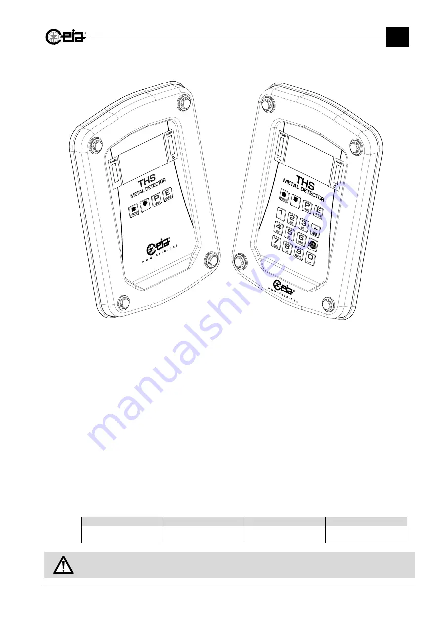
THS/21E - THS/21 


Instruction manual  

for installation, use  

and maintenance


Document 

Date 

Hardware 

Software 

FI002K0018v1530hUK 29/07/2020 

HV5.xx 

THSV5744 

ALMV5430 / ALMV5730 


Read this manual carefully before installing, operating or carrying out maintenance on the device. Keep the manual in a 

safe place for future reference and in perfect condition. This manual must accompany the device described herein in the 
case of change of ownership and until the device is decommissioned. 

Summary of Contents for THS/21

Page 1: ...ion use and maintenance Document Date Hardware Software FI002K0018v1530hUK 29 07 2020 HV5 xx THSV5744 ALMV5430 ALMV5730 Read this manual carefully before installing operating or carrying out maintenan...

Page 2: ...nt is marked with this symbol in the areas where there is the danger of unexpected bursts of compressed air Only trained maintenance personnel should carry out work in these areas The same symbol appe...

Page 3: ...2 6 1 4 THS G21 THS GMS21 THS G21E 35 2 6 1 5 THS G21 F THS GMS21 F THS G21E F 36 2 6 2 Power supply units 37 2 6 2 1 Control Power Box and Field Generator 37 2 6 2 2 Control Power Box with Remote Con...

Page 4: ...HS MN21 92 3 6 2 4 Conveyor Control System ALM card 94 3 6 3 SCD card 98 3 6 3 1 THS xx21E 98 3 6 3 2 THS xx21E 3F 99 3 6 3 3 THS xx21 100 3 6 3 4 THS xxMS21 101 3 6 3 5 THS MN21 102 3 6 3 6 Input for...

Page 5: ...stopping the conveyor belt 156 4 4 3 Adjustment of the belt speed 157 4 4 4 Automatic stop 157 4 4 5 Emergency stop 158 4 4 6 Alarm reset 158 4 4 7 Fault reset 158 4 4 8 Removing and emptying the rej...

Page 6: ...isposal of the device 201 5 8 1 Disposal of the device and of consumables with environmental impact 201 6 APPENDICES 203 6 1 CE Declaration of Conformity 203 6 1 1 THS 21E 203 6 1 2 THS 21 204 6 1 3 T...

Page 7: ...no binding character but are given for information purposes only REVISION HISTORY Rev Date Author Reference Description 1000 2010 09 16 TP2 SP First issue for all THS 21E and THS 21 models 1100 2012...

Page 8: ...ese instructions must be implemented throughout the life cycle of the product Installation Use and Maintenance Manual The purpose of the Installation Use and Maintenance Manual is to provide the infor...

Page 9: ...aintenance 1 SAFETY INSTRUCTIONS WARNINGS ORIGINAL INSTRUCTION 9 1 SAFETY INSTRUCTIONS WARNINGS All Safety Instructions and Warnings are reported on the proper Warnings Manual that shall be carefully...

Page 10: ...metal with the consequential signals to all devices connected to the Metal Detector The level of a signal produced by a metallic fragment depends on the metal kind on its dimensions and volume and may...

Page 11: ...ect product container are all fully certified for food safe applications 2 1 3 Products that can be inspected Parts of the Metal Detector and CEIA integrated systems which come in contact with product...

Page 12: ...nal units photocell ejector etc C Connecting cable D Tunnel E Stainless steel control panel fitted with alphanumeric display and a 4 key programming keyboard 2 2 2 THS 21 and THS MS21 The THS 21 is a...

Page 13: ...nular material liquids etc THS G21E A The Metal Detector Probe complete with electronic control unit SCD B The power supply box for connecting the device to mains power and to the external units photo...

Page 14: ...nce between the two versions is in the type and number of connections for external devices as detailed in the table below where all data related to the small size power supply unit card are also repor...

Page 15: ...y Unit The 00211AL_ card is used in OEM applications for integration in the customer s systems The card requires a power supply voltage of 24 V 20 30 VDC 2 2 6 4 Field Generator This unit is part of t...

Page 16: ...tal packaging single row or loose In vertical packaging single row In horizontal packaging single row or loose In horizontal packaging single or multiple row or loose In vertical packaging single row...

Page 17: ...option at the order stage to invert the transit direction with respect to the Detection Probe Control Panel From left to right From right to left Example with a THS FBB 2 3 1 2 Inverting the ejection...

Page 18: ...l C Main switch D Conveyor belt control panel E Synchronization photocell F External beacon G Emergency button H Reject bin K Rejected product bin lock or upon request solenoid lock L Ejection system...

Page 19: ...ollers with cover double rollers with cover P Output cover standard only ejection area Extended until belt end with inspection door and Emergency sensor E Synchronization photocell retro reflection re...

Page 20: ...anel C Main switch D Conveyor belt control panel E Synchronization photocell F External beacon G Emergency button H Reject bin K Rejected product bin lock or upon request solenoid lock L Ejection syst...

Page 21: ...tion system type reject pusher cylinder reject air jet H Reject bin standard size 400mm product input width P Output cover standard only ejection area E Synchronization photocell retro reflection retr...

Page 22: ...robe B Programming and control panel C Main switch D Conveyor belt control panel E Synchronization photocell F External beacon H Reject bin K Rejected product bin lock or upon request solenoid lock L...

Page 23: ...er double rollers with cover P Output cover standard only ejection area Extended until belt end with inspection door and Emergency sensor E Synchronization photocell retro reflection retro reflection...

Page 24: ...be B Programming and control panel C Main switch D Conveyor belt control panel E Synchronization photocell F External beacon G Emergency button H Reject bin J Magnetic safety sensor L Ejection system...

Page 25: ...height extension R Side panels for product containment L Ejection system type retracting belt H Reject bin standard size 400mm product input width P Output cover standard E Synchronization photocell r...

Page 26: ...ontrol panel C Main switch D Conveyor belt control panel E Synchronization photocell F External beacon H Reject bin K Rejected product bin lock or upon request solenoid lock L Ejection system M Suppor...

Page 27: ...e panels for product containment L Ejection system type reject pusher cylinder reject air jet H Reject bin standard size 400mm product input width P Output cover standard only ejection area E Synchron...

Page 28: ...h D Conveyor belt control panel E Synchronization photocell G Emergency button M Support feet to be fixed to the floor P Protection cover Q Encoder on request Available features and options Belt lengt...

Page 29: ...x All control power boxes including those fitted to integrated system have ID plates with the information shown in the examples below 31002xxxxxx 100 240 Vac 50 60 Hz 1ph x kA rms Symmetrical xx V max...

Page 30: ...4 CEIA conveyor structure CEIA integrated systems have an additional ID plate for the conveyor belt as shown in the example here THS FBB 31002xxxxxx 1500 x 300 2 5 Functional diagrams Legend CEIA IND...

Page 31: ...I002K0018v1530hUK THS 21 Instruction manual for installation use and maintenance 2 DESCRIPTION ORIGINAL INSTRUCTION 31 2 5 2 THS with Conveyor Control System 2 5 3 Integrated systems with Conveyor Bel...

Page 32: ...2 FI002K0018v1530hUK THS 21 Instruction manual for installation use and maintenance DESCRIPTION 32 ORIGINAL INSTRUCTION 2 5 4 THS RB and THS RBK...

Page 33: ...21 THS 21E THS 21E 3F Family DW DH TH DL FHL TP FHP FHD DC TW A 200 250 1000 100 125 150 175 395 290 190 105 TP 30 DW 60 205 DW 420 B 350 400 900 200 225 250 275 550 390 290 160 280 DW 520 C 450 500 1...

Page 34: ...INSTRUCTION 2 6 1 2 THS SL21 THSSL21E Family DW DH TH FD TW A 150 200 250 275 300 325 350 375 400 450 100 310 DW 50 DW 387 B 125 150 360 C 175 200 410 D 225 250 275 460 2 6 1 3 THS MN21 Model DW DH TH...

Page 35: ...SCRIPTION ORIGINAL INSTRUCTION 35 2 6 1 4 THS G21 THS GMS21 THS G21E Model T TW DH VL HL THS G21x 50 50 360 250 205 226 THS G21x 100 100 THS G21x 150 150 410 300 255 276 THS G21x 175 175 435 325 280 3...

Page 36: ...L VD THS G21x 150F 150 168 435 300 255 276 150 THS G21x 175F 175 193 460 325 280 301 162 5 THS G21x 200F 200 218 485 350 305 326 175 THS G21x 250F 250 268 535 400 355 376 200 On THS G21x xxF models ab...

Page 37: ...Instruction manual for installation use and maintenance 2 DESCRIPTION ORIGINAL INSTRUCTION 37 2 6 2 Power supply units 2 6 2 1 Control Power Box and Field Generator 2 6 2 2 Control Power Box with Rem...

Page 38: ...struction manual for installation use and maintenance DESCRIPTION 38 ORIGINAL INSTRUCTION 2 6 2 3 Control Power Box with Remote Control Unit THS 21 2 6 2 4 Conveyor Control System 2 6 2 5 Small size p...

Page 39: ...FI002K0018v1530hUK THS 21 Instruction manual for installation use and maintenance 2 DESCRIPTION ORIGINAL INSTRUCTION 39 2 6 3 Remote Control Unit 2 6 3 1 21E series 2 6 3 2 21 series...

Page 40: ...1115 500 7452 650 1330 1480 1125 1215 1800 200 7001 7751 8251 1505 350 1030 1180 825 915 590 1205 1305 300 450 1130 1280 925 1015 400 550 1230 1380 1025 1115 500 7452 650 1330 1480 1125 1215 Conveyor...

Page 41: ...B TW 3 BC DE CL feet extension castors fam C 75 125 250 1500 400 8751 9501 10001 1205 700 1050 590 1260 500 800 1150 1800 400 8751 9501 10001 1505 700 1050 590 1260 500 800 1150 2000 400 8751 9501 100...

Page 42: ...FBBV BL BW BH TA TB TW BC DE feet extension castors piston air blow 75 125 250 1500 150 8751 10001 1205 660 970 765 600 1260 Not available 1 75 Dimensions in mm 2 6 4 3 THS FBV BL BW BH TA TB TW BC DE...

Page 43: ...FI002K0018v1530hUK THS 21 Instruction manual for installation use and maintenance 2 DESCRIPTION ORIGINAL INSTRUCTION 43 2 6 4 4 THS MBB With Family A and B Probes...

Page 44: ...1 8251 1505 350 1030 1180 825 915 590 1205 1305 300 450 1130 1280 925 1015 400 550 1230 1380 1025 1115 500 7452 650 1330 1480 1125 1215 600 750 Conveyor belt with nominal height 875 1030 200 8751 9501...

Page 45: ...NAL INSTRUCTION 45 With Family C Probes BL BW BH TA TB TW BC DE CL feet extension castors fam C 75 125 250 1530 400 8751 9501 10001 1205 700 1050 590 1270 500 800 1150 600 900 1250 1830 400 8751 9501...

Page 46: ...CRIPTION 46 ORIGINAL INSTRUCTION 2 6 4 5 THS MBR BL BW BH TA TB TW BC DE CL 1700 300 8751 1205 450 875 598 1330 450 600 1025 600 750 1175 800 950 1375 2000 300 8751 1505 450 875 591 1587 450 600 1025...

Page 47: ...INSTRUCTION 47 2 6 4 6 THS RB and THS RBK BL BW BH FL FW TW BC UH 800 200 875 50 400 BW 250 BW 485 BH 175 65 90 115 140 165 300 400 2 7 Options and Accessories For the list of options and accessories...

Page 48: ...E series Max number of Products 500 250 Max number of Events 10 000 100 000 with 1 000 100 000 with Events type Metal Alarm Test results Programming acces exit Parameter modifications Diagnosis messag...

Page 49: ...rd Power supply voltage 20 30 Vdc o Vac 2A max Protection degree 21 series IP66 IP69K On UL versions the and have a type 4X 12 certified degree of protection 21E series IP65 Dimensions and Weights Use...

Page 50: ...ressure Ejector position check Bin full Bin absent Encoder Safety functions Conveyor belt stop Cat 0 EN60201 1 PL Performance Level c EN ISO 13849 1 Pneumatic actuator stop Programming Local Control p...

Page 51: ...awings included with the System Weight With package Indicated outside the package Net Indicated on FAT document enclosed with the System Environmental conditions Use Indoor Industrial environment NOT...

Page 52: ...minimum space for the System installation takes into account the overall dimensions of the System and the surrounding minimum space that must be free for a correct use of the System itself Refers to t...

Page 53: ...stomers conveyor belts For the installation checks you need to be able to switch on the system understand the signals given during use and set the applicable operating parameters These operations are...

Page 54: ...nfiguration par 3 12 S Metal Detector Probe P Stainless steel support structure E Ejection system with metallic moving parts M Conveyor belt motor see paragraph 3 1 3 5 t Conveyor belt mat see paragra...

Page 55: ...paragraph 3 3 1 2 Fi Insulation of metal flanges see paragraph 3 1 2 6 DH Diameter of the Probe S transit tunnel Df Respect distance between Probe S and any static metal masses see table below Dm Res...

Page 56: ...er to ensure that the detector does not oscillate causing false alarms The load bearing structures of the transport system must be stable and not subject to detectable vibration when the belt is movin...

Page 57: ...ns to avoid its cut in case it has to be disassembled during cleaning or periodical maintenance operations Consider also proper systems to ease its disassembly Belt and insulating sheet must not touch...

Page 58: ...the Probe be of insulating material All models THS MN21 D 1 5 DH 3 DH1 1 Use non magnetic steel bearings Rollers made from insulating material with metal bearings I insulated support C non insulated...

Page 59: ...L input The photocell must be positioned at a height where the beam is always interrupted by the objects transiting on the conveyor belt It is also recommended to place it at the minimum possible dist...

Page 60: ...exit from the Probe EM S SB N conveyor belt S electronics unit F photocell PL length of package E ejection area DW length of Probe ED distance photocell ejector 6m max Dp distance between packs PL ED...

Page 61: ...rrect installation and configuration par 3 12 of the System 3 1 3 1 Power supply of other devices Connect the System power supply and ground connection directly and solely to the main electrical panel...

Page 62: ...any electrical phenomena as a result of the device switching operations Keep the encoder and its cable at a distance of at least 2 x DH from the Probe aperture Keep a minimum distance between the Met...

Page 63: ...QE M1 M2 MD POWER BOX Connect the motors driven by the inverter of the Metal Detector transport system and near it using screened triphase earth cable the frame of the motor and the screen must be con...

Page 64: ...late the metal frame of the motor from the conveyor belt structure in order to avoid potentially critical ground loops connect the motor to the ground only through the Inverter PE terminal Use for the...

Page 65: ...Only cable with an outer diameter between M16 3 0 10 0 mm M20 5 0 13 0 mm M25 8 0 17 0 mm Close all non used cable glands holes with the proper caps Do not use the device with not closed holes 3 1 3 7...

Page 66: ...bearing capacity Ensure that the load is balanced during handling and transport Other transport methods are forbidden Place the equipment still in its package as close as possible to the final instal...

Page 67: ...stallation Maintenance and Programming Manuals Quality Control Test Samples if ordered 3 2 1 4 Moving the Metal Detector Before you move the detector check its weight It could be too heavy to be handl...

Page 68: ...ge Packed integrated systems are bulky and heavy The centre of gravity of the packaging is not where it might appear from the outside of the packaging To ensure balanced lifting insert the forks in th...

Page 69: ...balanced during movement Avoid deforming the structure or its component parts If the system is fitted with castors ensure that these are released before you start moving the device When transporting a...

Page 70: ...h an unique code to download all Installation Maintenance and Programming Manuals Quality Control Test Samples if ordered 3 2 3 4 Moving the Metal Detector Before you move the detector check its weigh...

Page 71: ...ic spacer e Insulating bush WARNING The Detection Probe with rectangular opening is fitted with appropriate insulated support feet The Detection Probe structure is connected to earth with the connecti...

Page 72: ...the Probe not lower than 2 x DH For the fixing distances see the Dimensions section for the relevant model in chapter 2 Description of this manual During the installation procedure if the connection c...

Page 73: ...attached must ensure its stability Important When you adjust the height of the CEIA integrated system ensure that the sling surface remains parallel with the floor Do not install any device on the con...

Page 74: ...nal AM43 AM44 Actuator 3 4 2 2 Air jet ejection system Description Description P1 Compressed air supply AM15 Adjustable pressure switch optional AM40 Adjustable pressure regulator with return flow act...

Page 75: ...e unit to the compressed air supply A with an 8 mm diameter hose and a quick release connector 3 4 3 2 Air jet ejector Connect the unit to the compressed air supply A with a 10 mm diameter hose and a...

Page 76: ...locked with a bolt and a nut replaceable by the Customer with a padlock If necessary it is possible to adjust it up to a maximum of 0 6 MPa 1 Remove the lock be it the factory bolt or the padlock prov...

Page 77: ...itable for the product to be ejected you can adjust it using the IN and OUT flow regulators AM42 and AM43 on the cylinder Using a N 32 wrench unlock and remove the piston carter nut Pull the carter ou...

Page 78: ...ide the carter accessible from below then loose nut B also Open the carter by rotating them on the lower pivots Loose the blocking nut A adjust the air flow by rotating the knob B then lock again tigh...

Page 79: ...ty of the Customer 3 5 Electrical Installation 3 5 1 Installing connecting cables The following instructions refer to the installation of connecting cables to external equipment and servo systems Only...

Page 80: ...sed only in conjunction with the Ejection Confirmation input and with ejectors compatible with this check J16 N A EJECTOR POSITION CHECK Ejection check Indicates that contaminated product has passed b...

Page 81: ...only with Conveyor Control System or encoder Signal of moving belt e g for consent to an upstream belt or other machine in the line J01 N A PREC CONV RELAY Machine Ready relay Signal that Metal Detec...

Page 82: ...Barcode reader Connection to a barcode reader upstream of the Metal Detector for automatic selection of the detection parameters in accordance with the barcode of the product in transit J11 N A Auxil...

Page 83: ...ncy button to access the contacts inside Release the pre pressed hole on the emergency button container Insert an M20 cable gland and lock on the hole Insert a cable of the right size for the gland so...

Page 84: ...nd An unscreened cable might cause disturbances to the Metal Detector Take the ferrite supplied and insert the three wires inside as shown to create a coil The ferrite must be placed as near as possib...

Page 85: ...ect a cable with wire minimum cross section of 2 5 mm AWG14 maximum 4 mm2 AWG10 and pass it through the suitably sized cable gland Control Power Box Connect the mains power supply to the input L1 and...

Page 86: ...e lower than that required under the current rules of the country of installation and in any case below 5 ohm Control Power Box Conveyor Control System 3 5 6 2 Power Switch On the Conveyor Control Sys...

Page 87: ...ce Test 3 6 1 Functional diagrams 3 6 1 1 Control Power Box MAINS 100 240Vac 50 60Hz 1ph MAIN OVERCURRENT PROTECTION TO BE PROVIDED ON SITE MAX 15 A CC CLASS FUSE FOR UL508A APPLICATIONS MAX 16 A FUSE...

Page 88: ...l System MAINS 200 240Vac 50 60Hz 100 120Vac for 115V version MAIN OVERCURRENT PROTECTION TO BE PROVIDED ON SITE MAX 15 A CC CLASS FUSE FOR UL508A APPLICATIONS MAX 16 A FUSE FOR CE APPLICATIONS PROTEC...

Page 89: ...equipped with RCU card MAIN OVERCURRENT PROTECTION TO BE PROVIDED ON SITE MAX 15 A CC CLASS FUSE FOR UL508A APPLICATIONS MAX 16 A FUSE FOR CE APPLICATIONS MAIN DISCONNECT SWITCH TO BE PROVIDED ON SIT...

Page 90: ...IN OVERCURRENT PROTECTION TO BE PROVIDED ON SITE MAX 15 A CC CLASS FUSE FOR UL508A APPLICATIONS MAX 16 A FUSE FOR CE APPLICATIONS MAIN DISCONNECT SWITCH TO BE PROVIDED ON SITE PROTECTION DE LIGNE A MA...

Page 91: ...l for installation use and maintenance 3 INSTALLATION ORIGINAL INSTRUCTION 91 3 6 2 2 Small Size Power Supply card E2888 AC DC 24V recommended module not provided Wrap the output wires of the AC DC mo...

Page 92: ...1 Instruction manual for installation use and maintenance INSTALLATION 92 ORIGINAL INSTRUCTION 3 6 2 3 Field Generator for THS MN21 E2559A Trimmers on AM3 and AM2 are preset to obtain an output voltag...

Page 93: ...FI002K0018v1530hUK THS 21 Instruction manual for installation use and maintenance 3 INSTALLATION ORIGINAL INSTRUCTION 93...

Page 94: ...veyor Control System ALM card 230 V version E3287 MAIN OVERCURRENT PROTECTION TO BE PROVIDED ON SITE MAX 15 A CC CLASS FUSE FOR UL508A APPLICATIONS MAX 16 A FUSE FOR CE APPLICATIONS PROTECTION DE LIGN...

Page 95: ...FI002K0018v1530hUK THS 21 Instruction manual for installation use and maintenance 3 INSTALLATION ORIGINAL INSTRUCTION 95...

Page 96: ...tenance INSTALLATION 96 ORIGINAL INSTRUCTION 115 V version E3176 MAIN OVERCURRENT PROTECTION TO BE PROVIDED ON SITE MAX 15 A CC CLASS FUSE FOR UL508A APPLICATIONS PROTECTION DE LIGNE A MAXIMUM DE COUR...

Page 97: ...FI002K0018v1530hUK THS 21 Instruction manual for installation use and maintenance 3 INSTALLATION ORIGINAL INSTRUCTION 97...

Page 98: ...3 FI002K0018v1530hUK THS 21 Instruction manual for installation use and maintenance INSTALLATION 98 ORIGINAL INSTRUCTION 3 6 3 SCD card 3 6 3 1 THS xx21E...

Page 99: ...FI002K0018v1530hUK THS 21 Instruction manual for installation use and maintenance 3 INSTALLATION ORIGINAL INSTRUCTION 99 3 6 3 2 THS xx21E 3F...

Page 100: ...3 FI002K0018v1530hUK THS 21 Instruction manual for installation use and maintenance INSTALLATION 100 ORIGINAL INSTRUCTION 3 6 3 3 THS xx21...

Page 101: ...FI002K0018v1530hUK THS 21 Instruction manual for installation use and maintenance 3 INSTALLATION ORIGINAL INSTRUCTION 101 3 6 3 4 THS xxMS21...

Page 102: ...struction manual for installation use and maintenance INSTALLATION 102 ORIGINAL INSTRUCTION 3 6 3 5 THS MN21 3 6 3 6 Input for speed control through a 0 10V analogic signal 1 2 3 4 5 ANALOG COMMON ANA...

Page 103: ...ative to the products the Metal Detector configuration and occurred events An internal memory where the occurred events are saved up to 100 000 events AM31 External USB optional Perform the connection...

Page 104: ...to the Electric Diagram supplied with the Manual 3 6 5 1 THS FBB THS MBB THS FBV THS FBBV without SCN board AM11 Synchronization photocell AM12 Encoder sick AM13 Ejection confirmation photocell mount...

Page 105: ...anuale istruzioni per l installazione l uso e la manutenzione THS 3 INSTALLAZIONE ORIGINAL INSTRUCTION 105 AM13 Ejection Confirmation photocells AM19 AM25 Signalling lamp RG Roller ground connection T...

Page 106: ...IGINAL INSTRUCTION 3 6 5 2 THS FBB THS MBB THS FBV THS FBBV with SCN board CCS Conveyor Control System EM1 Emergency button AM25 Flashing lamp AM11 Synchronization photocell AM12 Encoder sick MC Motor...

Page 107: ...rmation photocells AM19 AM14 Bin Full photocell AM14 Bin Full photocells AM20 AM15 Pressure switch AM16 Ejection check Y1 Ejector activation Y2 Ejector deactivation not used with air blow SM17 Bin loc...

Page 108: ...ruction manual for installation use and maintenance INSTALLAZIONE 108 ORIGINAL INSTRUCTION 3 6 5 3 THS MBR CCS Conveyor Control System EM1 Emergency buttons AM25 Flashing lamp AM11 Synchronization pho...

Page 109: ...CN SCN Connections box AM28 Ejection Confirmation sensor AM14 Bin Full photocell AM15 Pressure switch AM29 Ejector position check sensor SM19 Bin lock connected to the Emergency circuit SM23 Bin absen...

Page 110: ...elay 8 NC N C contact 9 NO N O contact J02 1 C Output common 30 V AC DC 2 5A Ready relay 2 NC N C contact 3 NO N O contact 4 C Output common Ejection relay 5 NC N C contact 6 NO N O contact 7 C Output...

Page 111: ...igher than 150 mA an external power supply must be used leaving pin 5 disconnected 2 GND GND 3 RXD Data 4 TXD Data 5 24V BC Reader 24V 150 mA max J12 1 GND GND Auxiliary serial port communication 2 TX...

Page 112: ...stem check sensor 2 Ej check Input 3 Vin 24V 2 4 0V 0V Connection of ejector position check sensor 5 EJ POS CHK Input 6 Vin 24V 2 7 0V 0V Connection of a button NA to activate Test request 8 IN AUX1 I...

Page 113: ...LAMP Output Fault signal 0 24V 4 YELLOW L Output Alarm signal 0 24V 5 BLUE LAMP Output Test req signal 0 24V 6 HORN Output Sound signal 0 24V 7 SPARE LAMP Output Reset backlight 0 24V Backlighting of...

Page 114: ...3 NO N O contact 4 C Output common Ejector relay 5 NC N C contact 6 NO N O contact J2 1 GND Reserved GND Reserved for RCU connection 2 GND GND 3 TXD Data 4 RXD Data 5 5V 5 V 6 V 24 V J3 1 24 V 100 mA...

Page 115: ...ated if the device is connected wrongly The input devices may be simple contacts relays or buttons or sensors with a transistor output with saturation voltage less than 1 V of the push pull type PNP o...

Page 116: ...switch sensor for confirmation of correct activation of the ejector ECK EJECTION CHECK Check for complete ejection of product Sensor used to verify that during the ejection cycle any other prodyuct is...

Page 117: ...high accuracy is required for product in packs and correctly aligned on the conveyor belt Install the photocell as close as possible to the Detection Probe at the entrance or the exit in the direction...

Page 118: ...ve with the metal Detector operative and it is immediately deactivated in case of Diagnosis status and or Metal Detector shut down Relay Activation condition Notes Closed contact activated relay READY...

Page 119: ...on program like Windows Hyperterminal can also be used Read the Programming Manual for further information 3 8 2 BT Wireless Communication The programming can be also performed through a BT Wireless c...

Page 120: ...ust be set These operations which are listed on the first page of the Installation section are described below in this section Verify that the power supply door is properly closed before starting the...

Page 121: ...hat set with IE ENCODER IN_AUX NO 4 Enter the Configuration adv I O Status Outputs menu and check also that each connected output has been activated changing the status of the corresponding line from...

Page 122: ...ransport and consider the Metal Detector synchronization with the product transport device see Timings and Following Conveyor enabling Set BL and BM values as close as possible to BS according to the...

Page 123: ...pulses per rotation PPR as defined by this formula max max 180 v DI PPR Start the transport enter the I O Status Measures menu and verify using a tachymeter that the speed measured Speed corresponds...

Page 124: ...tal Detector and the Ejection Check photocell 0 6000 mm N conveyor belt S electronics unit F photocell ECPD distance photocell Probe 3 9 9 Ejection mode The ejection settings enable after an alarm due...

Page 125: ...istance of the contaminated pack stop area from the centre of the Probe 0 6000 mm Generic example S Metal Detector Probe N Conveyor belt C Contaminated pack DW Detector width ED Ejector distance After...

Page 126: ...hotocell 0 6000 mm Photocell at the entrance PH IN Generic example S Metal Detector Probe N Conveyor belt C Contaminated pack F Synchronization photocell PL Pack length DW Detector width ED Ejection d...

Page 127: ...ystems THS MBB THS MBR or on all the other systems involving inversion of the direction of travel Operation with automatic ejection of contaminated material by reversing the belt direction Programming...

Page 128: ...ting Ejection Ejection mode EM Automatic removal of contaminated material with alarm synchronization F Ejection Ej distance ED Distance of ejection area from the centre of the Probe 0 6000 mm Ejection...

Page 129: ...Ejection Ejection mode EM Automatic removal of contaminated material with contaminated pack synchronization S Ejection Ej distance ED Distance of the ejector from the synchronization photocell 0 6000...

Page 130: ...on mode only if a Synchronization photocell is present the product transit shall also be correctly aligned in front of the photocell and the operational spacing between packs shall be compatible with...

Page 131: ...ms fitted with an ejector this mode determines the automatic ejection and removal of the contaminated material in the reject bin Programming menu Remote parameter Description Setting Ejection Ejection...

Page 132: ...larm the ejector will be activated for the time of the alarm and to eject all products in the R area Minimum removal area PL DW PL A control can be introduced from the photocell of two areas alongside...

Page 133: ...owing code formats are supported XXXXXX CR XXXXXX CR LF STX XXXXXX ETX Where XXXXXX is a string of 48 characters max Refers to the electrical connections description par 3 7 1 for the requested electr...

Page 134: ...product transport activated For systems fitted with a Conveyor Control System or Control Power Box with encoder the timings are based on the actual speed of the conveying system For systems with a Co...

Page 135: ...NV RELAY Conveyor belt movement ALARM RELAY External alarm signalling EJECT RELAY Ejection signal RESET Alarm reset Start button Belt restart YELLOW LAMP Alarm beacon operation Control Power Box Wavef...

Page 136: ...ignal over the alarm threshold with transport activated Metal alarm PHOTOCELL Pack in front of the photocell at the entrance in the example PREC CONV RELAY Conveyor belt movement ALARM RELAY External...

Page 137: ...cceleration If an Alarm is still present after the belt moved backward for a space ED the belt will move another ED space backward 3 10 4 EM F Generic example S Metal Detector Probe N Conveyor belt C...

Page 138: ...r the alarm threshold with transport activated Metal alarm PHOTOCELL Pack in front of the photocell at the entrance in the example ALARM RELAY External alarm signalling EJECT RELAY Ejection signal YEL...

Page 139: ...activate the ejector at the start of the removal area R or Re b Calculated automatically for the complete removal of area R or Re alarm time time needed for the complete removal The effective removal...

Page 140: ...ns inhibited The Metal Detector will become active again after IN seconds of the deactivation of the input as shown in the diagram below Waveform Description INHIBITION Metal Detector inhibition Metal...

Page 141: ...movement start FOLLOWING CONVEYOR Consent from machine Conveyor belt status Belt in movement or stopped With RE OFF to restart the conveyor belt press the START button In systems with a Control Power...

Page 142: ...stems with a Conveyor Control System activation of the PREC_CONV relay coincides with the belt movement Input Description Remote param Values PREC_CONV RELAY Belt in movement PC Activation ON OFF Conv...

Page 143: ...working of all the emergency buttons connected to the System 5 Verification of the operative conditions and of detection with product Set the detection parameters based on the product to be inspected...

Page 144: ...sword Direct access without a password user 000000 must not be available It is up to the Administrator to Activate the monitoring of any unauthorized attempts to access programming FLR ON In the case...

Page 145: ...nd from the web page select the local file to be analysed and send it for the validation Send button subsequently press the Check Digital Signature button If the file is valid the message Valid Digita...

Page 146: ...h RCU remote control unit A POWER A green indicator indicates the presence of power B ALARM A red indicator indicates the detection of a metal fragment or a fault in the unit C Display Displays the me...

Page 147: ...ustic warning device buzzer which sounds to indicate a fault or metal detection The external beacon by default sounds only to indicate faults but can also be programmed to sound when the detector dete...

Page 148: ...nd exit the programming step Return from the submenus to the previous menu Exit from the Metal Detector Status display Cancel the last character entered Scroll through a list of instructions Select th...

Page 149: ...orward Decrease speed Manual reverse Metal Detector alarm reset Can be disabled See Programming Manual Emergency reset The motor speed control keys depending on UD and MM parameters can have different...

Page 150: ...t the reject bin is in position and correctly fastened 4 Floor fixing If requested check that the structure is firmly anchored to the floor In case of castors check that they are locked 5 Obstructions...

Page 151: ...itching on Do not start a system whose safety systems are not fully efficient Do not tamper with safety devices The manufacturer declines all liability for damage resulting from tampering with safety...

Page 152: ...the power supply unit On integrated systems the display shows the message EMERGENCY RESET and waits for you to press the Emergency Reset key After this the following display appears THS xx21E THS xx2...

Page 153: ...of the bar THS xx21E THS xx21 THS xx21E V5 xxx Prod PROD01 CEIA THS xx21 ALM V5 xxx THS V5 xxx Product PROD01 Signal well below the threshold level THS xx21E V5 xxx Prod PROD01 CEIA THS xx21 ALM V5 x...

Page 154: ...Detection Reset Products Autolearn Detection Ejection The Metal Detector has been set to programming mode accessible parameters can be modified TEST Prod PROD01 TEST Product PROD01 The Metal Detector...

Page 155: ...n related to its functioning status THS xx21E THS xx21 THS xx21E V5 xxx Product PROD01 CEIA THS xx21 ALM V5 xxx THS V5 xxx Product PROD01 To show the Metal Detector activity the colons beside the sele...

Page 156: ...tal Detector Probe N Conveyor belt F Synchronization photocell I Correct area where the product shall be loaded 4 4 2 Starting stopping the conveyor belt With the power supply on and with the motor st...

Page 157: ...he Speed reading indicates the speed set and varies in real time when the and keys are pressed Any modification of the speed is stored to memory as a parameter specific to the current product type and...

Page 158: ...is not stopped and the contaminated product is sent into a reject bin which should be emptied at regular intervals by the operator In this case the System resets automatically in operation with manua...

Page 159: ...g You must then open the bin within the preset Unlock bin time default value 10 s max value 30 s and empty it At the end of the operation close the reject bin back 4 4 8 1 THS FBB THS MBB THS FBV and...

Page 160: ...eypad or using the and keys and confirming each character with the key Password __ After the password has been entered the Metal Detector is inhibited access to programming is given and the display sh...

Page 161: ...Press The display will show a list of all stored products in alphabetical order Product DEFAULT PROD01 PROD02 Product DEFAULT PROD01 PROD02 POW003 SUGAR Search _________ Use the arrow keys to scroll...

Page 162: ...nabled to this function predefined user 000004 For any information about programming the test type and eventually its periodic request and for the automatic test mode refers to the Programming Manual...

Page 163: ...ible for following its own QA procedures The test samples must be used only under the environmental conditions indicated as operative see Technical Characteristics and in compliance with QA procedures...

Page 164: ...LED for Sample too big THS 21E THS 21 The signal given by the sample is considered too high to perform a valid test according to the maximum allowed level see Q C setup menu TEST FE FAILED SAMPLE TOO...

Page 165: ...t 0 80 NO 3 NFE test 1 00 SS test 1 20 3 SYNC PHOTOC ERROR FE Test 0 80 NO 3 NFE Test 1 00 SS test 1 20 3 SYNC PHOTOC ERROR TEST ABORTED If the self diagnosis system detects a fault of any kind the te...

Page 166: ...tic tests are performed only if the signal provided by the samples during the previous manual test is at least 3dB Otherwise at the next scheduled test request the Metal Detector will require a new ma...

Page 167: ...al for installation use and maintenance 4 USE OF THE DEVICE ORIGINAL INSTRUCTION 167 TEST FAILED THS 21E THS 21 If the test fails the cause will be displayed AUTOM TEST FAILED NO EJECT CONFIRM AUTOM T...

Page 168: ...ginning of each shift Operator Section 5 2 1 External cleaning Section 5 2 2 Cleaning of the parts in contact with the product On changing product type Operator Periodically Clamping of terminals for...

Page 169: ...em protection degree 5 2 2 Cleaning instructions for the parts in contact with the product In order to clean the parts in contact with the product follow the procedure described in section 5 2 3 Only...

Page 170: ...ary for its cleaning or replacement If the conveyor belt is fitted with an ejection system perform the following steps before continuing Remove all supply sources by means of the LOTO devices and lock...

Page 171: ...and pull it out of the belt Remove the drive roller from the guides on the other side of the motor thus freeing the support surface Raise the support surface from its position and from the belt Open t...

Page 172: ...ver is now free Remove it from its position Using a N 13 wrench loosen the two bolts in the bottom part of the ejector support without removing them Using two N 10 wrenches remove the two bolts fixing...

Page 173: ...e conveyor belt Repeat the last three steps with the input roller group Remove the input sliding surface from the joint with the output sliding surface as shown above Remove the input sliding surface...

Page 174: ...n roller shaft Using a n 17 wrench unlock the motor roller by removing the three indicated bolts Push the motor roller horizontally out of its position Remove the motor roller from under the conveyor...

Page 175: ...the hinges as far as possible Use a screwdriver to push the rod past the retention feature Ensure the rod is fully inserted Flush Grid modular belt Insert a screwdriver between two flush edges Twist...

Page 176: ...RB Remove the four locking pins Lift up the belt block from its housing Remove the belt block from the detection tunnel Follow the procedure in reverse to re assembly the conveyor belt Pay attention...

Page 177: ...t by lowering the idle roller support Start the Conveyor belt and check that the belt is correctly centered if the belt starts to move towards the right or the left side adjust by rotating clockwise t...

Page 178: ...ects metal masses Control panel fault Check the connections between the ALM card and the RCU card on the or on the Remote Control Unit RCU If the problem persists contact Assistance Service Display OF...

Page 179: ...for a possible belt contamination see 5 5 4 Metal Detector ALARM when transport stopped Adjacent Metal Detector interference Check that adjacent Metal Detectors are set to different transmission chan...

Page 180: ...erload due to excessive weight of the product or to conditions that cause an excessive increase in the adhesion of the belt with the sliding surface Check that the belt is correctly installed and tens...

Page 181: ...4 1 Changing fuses The figure shows the position and rating of the fuses fitted to the device Refers to electrical diagrams too Ref Description Fuse type Electrical diagram reference A Relays contacts...

Page 182: ...move the internal connectors J13 and J15 shown in the figure In case of electric screwdrivers operate them at reduced speed to avoid the loss of the bolt stop rings located on the back of the panel Us...

Page 183: ...the electrical diagram for the relevant THS model for the correct positioning of the terminals Reconnect the terminals shown next to connector J13 Reinsert the connectors J13 and J15 shown in the figu...

Page 184: ...ON and exit Programming The message TA Autolearn will appear on the display press down firmly for at least a second on the Probe as shown alongside do not press the centre line 3 Repeat the procedure...

Page 185: ...sion TX OFF the contributions of this type of noise are not visible anymore in the bargraph If the noise is not immediately identifiable the Metal Detector has some procedures to be performed with the...

Page 186: ...patibility INSUFFICIENT SUFFICIENT GOOD This result takes into account the actual Metal Detector settings however its correct functionality needs to be verified including with product in transit 5 5 2...

Page 187: ...e due to the transport i e inverter and motor connection Generic electrical noise due to any machine other than the one activated during the procedure Generic mechanical noise i e due to vibrating or...

Page 188: ...y It is recommended to periodically check the belt status cleaning and expecially for flat belts replacing it as also indicated in the Maintenance procedures for CEIA Integrated Systems In case of a C...

Page 189: ...onveyor belt is stopped programmable the ejection system is activated programmable The following is the complete description of Diagnosis and their possible corrective actions After removing the cause...

Page 190: ...d motor If the problem persists contact Assistance Service F8 Heat sink over temperature Check for blocked or dirty Inverter heat sink fins Check the fan F13 Earth fault Check the motor and external w...

Page 191: ...the problem persists contact Assistance Service PROBE FAULT x Connections of the Probe cable interrupted or Probe faulty X code for fault identification Check the Probe cable wiring connections with t...

Page 192: ...ult is due to this only the message is shown without the fault status being activated RESET EMERGENCY A manual reset is required after the emergency condition has been removed or when starting the Sys...

Page 193: ...heck the presence of a big metallic mass in the product in transit or that the alarm was not caused accidentally by an operator If needed the diagnosis can be deactivated by setting ATBT 0 CEN BELT FA...

Page 194: ...CONFIRM Ejection of the product in the bin not occurred within the programmed time limit CT Check the correct electric and mechanical installation the correct pneumatic setup and activation of the ej...

Page 195: ...SAFE FAILED One of the Tests of the Fail Safe Test is failed Check the correct operation and programming of involved sensors After the reset it is possible to perform the test again SYNC PHOTOC FAULT...

Page 196: ...Failed reading of the Synchronization photocell according to the reading of the Ejection Check photocell Sincronizzazione with PAT 1 Check that tha package will be correctly detected from both photoc...

Page 197: ...the maximum set EMEX EVENT BUFFER FULL Event memory buffer is full The Head of Quality Control or the Data management Supervisor shall print the Events or save them on file then confirm the operation...

Page 198: ...rtual remoting or if the virtual display has been activated once connected to the Web Server Detect inhibited The Metal Detector is inhibited by external device connected to the INHIBITION input or at...

Page 199: ...re performing any operation Uninstall the Probe and the Power Supply Box from the production line and place them apart 5 7 2 Packing 5 7 2 1 Probes Place the Probe on the wooden base Place the manuals...

Page 200: ...al beams of the system Pass two straps around the top part alongside the A and three straps around the bottom beams B Do not pass the straps around the conveyor belt Place any accessories inside the r...

Page 201: ...nd the horizontal beams of the system as indicated above Do not pass the straps around the conveyor belt Fit the original cardboard box and fix it at the bottom to the pallet Fix the box to the pallet...

Page 202: ...5 FI002K0018v1530hUK THS 21 Instruction manual for installation use and maintenance MAINTENANCE 202 ORIGINAL INSTRUCTION Page left intentionally blank...

Page 203: ...FI002K0018v1530hUK THS 21 Instruction manual for installation use and maintenance 6 APPENDICES ORIGINAL INSTRUCTION 203 6 APPENDICES 6 1 CE Declaration of Conformity 6 1 1 THS 21E...

Page 204: ...6 FI002K0018v1530hUK THS 21 Instruction manual for installation use and maintenance APPENDICES 204 ORIGINAL INSTRUCTION 6 1 2 THS 21...

Page 205: ...FI002K0018v1530hUK THS 21 Instruction manual for installation use and maintenance 6 APPENDICES ORIGINAL INSTRUCTION 205 6 1 3 THS G21...

Page 206: ...6 FI002K0018v1530hUK THS 21 Instruction manual for installation use and maintenance APPENDICES 206 ORIGINAL INSTRUCTION 6 1 4 THS G21E...

Page 207: ...FI002K0018v1530hUK THS 21 Instruction manual for installation use and maintenance 6 APPENDICES ORIGINAL INSTRUCTION 207 6 1 5 THS GMS21...

Page 208: ...6 FI002K0018v1530hUK THS 21 Instruction manual for installation use and maintenance APPENDICES 208 ORIGINAL INSTRUCTION 6 1 6 THS MS21...

Page 209: ...FI002K0018v1530hUK THS 21 Instruction manual for installation use and maintenance 6 APPENDICES ORIGINAL INSTRUCTION 209 6 1 7 THS MN21...

Page 210: ...THS FBV and THS RB Originals of the CE Declaration of Conformity for each model are provided with the documentation The following in example is the model of the Declaration of Conformity CE provided...

Reviews: