background image

C-9875


www.cebekit.es


[email protected]


Line tracker Robot (with infrared system) 


Arduino System 


These instructions indicate how to build the same Arduino-type smart robot vehicle. It states how to 

install step by step robot chassis, Arduino compatible motherboard, Shield module, geared motors, battery 
holder and the other accessories as well as their wiring system. 

With this project, you will learn how to program the Arduino system and its learning platform. 
It should be noted that to assemble this kit, 

 only a screwdriver is needed, NOT INCLUDED


included. All electrical and electronic 

parts can be connected or screwed

 into a terminal block or Clema. 

The system of infrared light sensors which are installed on the front part basis, detects the black line 

that you done on the floor with an adhesive tape forming a way. The intelligent robot will perfectly follow the 
drawn path as complicated or long as it is. 


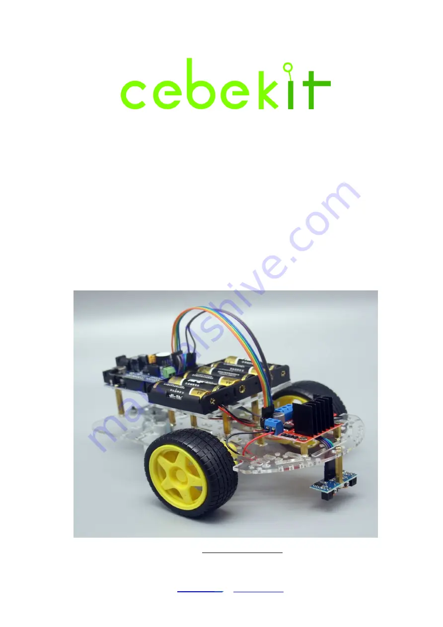
Views of the built robot


Summary of Contents for C-9875

Page 1: ...h this project you will learn how to program the Arduino system and its learning platform It should be noted that to assemble this kit only a screwdriver is needed NOT INCLUDED included All electrical and electronic parts can be connected or screwed into a terminal block or Clema The system of infrared light sensors which are installed on the front part basis detects the black line that you done o...

Page 2: ...C 9875 www cebekit es sat fadisel com ...

Page 3: ...30mm 5 7 Control module for motors L298 1 20 Nut M3 12 8 Robot s Chassis Transparent Acrylic Plastic 3 mm 1 21 Screw M3 x 10 mm 3 9 Battery holder Acrylic Plastic 3 mm 1 22 Module double sensor Black line tracker 1 10 USB Line Connection cable Robot USB 1 23 Metal spacer M3 x 25 mm 1 11 Motor with reduction 1 48 With double axis and cables 2 24 Cable with connectors 4 poles Male Female 1 12 Porte ...

Page 4: ...lic support for motors 4 3 Gearbox motor with double axis and cables 2 4 Wheel Ø65mm with rubber tire 2 5 M3 30 mm screws 4 6 M3 Nuts 10 7 M3 8 mm screws 4 8 Robotic free wheel 1 9 Tool needed Screwdriver 1 Figure 1 1 Necessary pieces for the chassis assembly Before to start the assembly remove the acrylic protection film as it is indicated hereafter Figure 1 2 ...

Page 5: ... supports C Screws and nuts to fix motors to the supports Figure 1 4 Pay attention to motors details in order to place them in the correct position Figure 1 5 Motors Installation View from the bottom part of chassis motor side Mark the cables of each motor The red cable is always on the upper part Outgoing element It is recommended to fix the cable with a hot melt adhesive ...

Page 6: ...s the chassis seen from the side of the motors lower side The inverted L shaped groove indicates the correct position Figure 1 7 Insert one of the motor s support from the top of the chassis as shown in the figure Figure 1 8 Now place the motor as shown in Figures 1 4 and 1 5 of the attached picture The outgoing element must always remain on the outside of the chassis Then place the other support ...

Page 7: ...ightened because it is in abutment with the chassis Figure 1 10 Install the other motor following the same instructions as for the first one In the picture below you can see the correct chassis position indicated by the inverted L shaped groove View of the side of the motors If your chassis is assembled upside down it will necessary to be disassemble and correctly reassembled it see Figure 1 6 ...

Page 8: ...at fadisel com Robotic Free wheel Fix the wheel with M3 8 screws and M3 nuts as it is indicated on following figures Figure 1 11 Holes where must be fixed the wheel Figure 1 12 Wheel in its correct position before its fixing ...

Page 9: ...ww cebekit es sat fadisel com Figure 1 13 Nuts are placed on the lower parts of the chassis Figure 1 14 Insert by pressure the two large wheels on the outer axis of each gearbox motor Bottom view of the chassis ...

Page 10: ...cording to the following instructions Firstly First Strongly grasp the two circuit boards as shown in the picture Secondly Carefully separate the two plates by pulling on both circuits Thirdly Be careful not to damage or bend the connector contacts Check one by one that all pins are correctly aligned with the connector s holes in the main board These two points must be checked very carefully to av...

Page 11: ... electronic Circuit Arduino Uno Type We will use 1 Smart Robotic chassis with all wheels 1 2 Module Arduino Uno Type 1 3 M3 8 mm Screw 8 4 M3x25 mm Metal spacer 4 5 Necessary tools Screwdriver 1 Figure 2 1 Necessary pieces to install the main control circuit ...

Page 12: ...C 9875 www cebekit es sat fadisel com Figure 2 2 Fix the four cylindrical spacer as it is indicated on the figure Figure 2 3 Main control circuit indicating the four fixing points ...

Page 13: ...C 9875 www cebekit es sat fadisel com Figure 2 4 Main control circuit fixed with screws ...

Page 14: ...ontrol circuit 1 Before connecting carefully check the position of the Shield module and the main control circuit connector 2 Check one by one that all the pins are correctly aligned with the holes in the main control circuit connector Check one by one that all the pins are correctly aligned with the holes in the main control circuit connector These two points should be carefully checked to avoid ...

Page 15: ...om Step 4 Batteries holder We will use 1 Robot 1 2 Batteries holder 1 3 M3 25 mm Metal spacer 4 4 M3 10 mm screw 10 5 Support acrylic board of the batteries holder 1 6 M3 Nut 2 7 Necessary Tools Screwdriver 1 Figure 4 1 Necessary pieces ...

Page 16: ...C 9875 www cebekit es sat fadisel com Figure 4 2 Spacers location Figure 4 3 Acrylic board fixing ...

Page 17: ...C 9875 www cebekit es sat fadisel com Figure 4 4 Preparation to fix the batteries holder Figure 4 5 Batteries holder once screwed7fixed ...

Page 18: ... Control Circuit of motors We will use 1 Robot 1 2 Control circuit of motors 1 3 M3 10 mm Metal spacer 4 4 M3 10 mm Screw 4 5 M3 8 mm Screw 4 6 Necessary tools Screwdriver 1 Figure 5 1 Pieces that we will use to fix the control circuit of motors ...

Page 19: ...C 9875 www cebekit es sat fadisel com Figure 5 2 Spacers positions Figure 5 3 Control Circuit once fixed ...

Page 20: ...t fadisel com Step 6 Black lines follower We will use 1 Basic Robot previously assembled 1 2 Black Line follower Module 1 3 M3 25 mm Metal spacer 1 4 M3 10 mm Screw 2 5 Necessary tolls Screwdriver 1 Figure 6 1 Necessary pieces ...

Page 21: ... cebekit es sat fadisel com Figure 6 2 Follower module once fixed to the spacer Figure 6 3 Line follower Module once fixed to the robot superior inferior views Attention to the position Do not install upside down ...

Page 22: ...ing 1 Connection of the Batteries holder Figure 7 1 Batteries holder wiring Batteries holder Circuit Arduino UNO type with the Shield module assembled RED Cable Terminal positive of the terminal block feed BLACK Cable Terminal negative of the terminal block feed ...

Page 23: ...HT Motor Motor Figure 7 3 Connect the left motor cables to the left side of the motor control module A1 and A2 terminals and those of the right motor to the right side B1 and B2 terminals Motor Motors Control Module Left motor Red cable Output terminal A A2 Left motor Black cable Output terminal A A1 Right motor Red cable Output terminal B B2 Right motor Black cable Output terminal B B1 ...

Page 24: ... www cebekit es sat fadisel com Step 8 Connection between motors control module and shield module Figure 8 1 Locations of contacts on the shield module Figure 8 2 Connector once connected on the Shield module ...

Page 25: ...bekit es sat fadisel com Figure 8 3 View of the other extremity of the connector connected to the motor control module Pay attention to the polarity Motors control module Shield Module IN1 D8 IN2 D9 IN3 D10 IN4 D11 ...

Page 26: ...male lug pins which are connected to the terminal block of the motors control module Figure 8 5 To connect the motors control module Attention polarity The positive pole 12V corresponds to the corner terminal of the motors control module see picture The terminal which is more centered on this terminal block is not used Figure 8 7 The other extremity of the cable has two female connectors that will...

Page 27: ... fadisel com Figure 8 8 View of the location of the terminals on the Shield module They are indicated on the module as 9V positive and GND negative Figure 8 9 Cable connection on the Shield module Pay attention to the polarity ...

Page 28: ...of the robot completely finished where it is possible to appreciate the power supply connection of the motors control module The colors of the cables may vary depending on the photographed model Motors control Module Shield Module 12V 9V Power Supply GND GN ...

Page 29: ...e 4 poles cable which has at one extremity a male connector and at the other extremity a female connector Figure 9 1 It is necessary to pass the male connector through the rectangular hole of the acrylic chassis Figure 9 2 Connect the connector to the sensor Pay attention to the polarity ...

Page 30: ...9875 www cebekit es sat fadisel com Figure 9 3 View of the connector and sensor Figure 9 4 View of the sensor correctly aligned the screw tight It is possible to appreciate the polarity of the connection ...

Page 31: ... the cable It is right next to the power supply connector of the motors control module Pay attention to the polarity Figure 9 6 Connector connected to the Shield module Line follower Infrared sensor Shield Module VCC 5V GND GND LO D4 RO D3 Note before activating the robot remove the protection label from the loudspeaker of the Shield module ...

Page 32: ...on the ground If the floor is not completely white it is recommended to use a tape of 20 to 25mm as the contrast with the black ribbon is important You can also draw a way on white paper or cardboard Once the way is defined place the robot on the line and it will follow the indicated way It may be necessary to adjust the potentiometers of the sensors see Figure 6 3 ...

Page 33: ...the robot 5 Install the software included in this CDROM Tracking ino 6 Disconnect the USB cable from the robot 7 Connect the robot switch ON position The indicator light will flash 8 Press the S1 button on the Shield module The robot buzzer will sound and it will be ready to be used 9 When you will be sufficiently comfortable with the handling of this robot if you wish you can learn to program wit...

Page 34: ...C 9875 www cebekit es sat fadisel com Diagram of the control board ...

Page 35: ...C 9875 www cebekit es sat fadisel com Diagram of the Shield module This is the complete drawing of the Shield module Depending on the selected kit only certain parts of the module will be used ...

Page 36: ...C 9875 www cebekit es sat fadisel com Drawing of the motors control module ...

Page 37: ...danger of asphyxiation Precautions with batteries 1 To place remove or change batteries it is necessary an adult to do this 2 Do not short circuit contacts of the batteries holder or their compartments 3 Remove old batteries from the device to prevent acid leakage 4 Never mix new and used batteries or batteries of different types 5 Never mix alkaline standard coal zinc or rechargeable nickel cadmi...

Reviews: