Caroma Invisi Series II, Installation Manual
The Caroma Invisi Series II is an innovative and high-quality bathroom fixture designed for ultimate comfort and efficiency. Enhance your bathroom experience with this sleek and space-saving product. Explore its features, installation instructions, and maintenance details in the comprehensive user manual available for free download at manualshive.com.
Share
Download


Reviews:
No comments
Related manuals for Invisi Series II
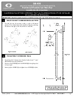
SB Series
Brand: California Faucets Pages: 2

8010
Brand: Jafar Pages: 12
BarkLimiter
Brand: Garmin Pages: 6
BarkLimiter
Brand: Garmin Pages: 12

CHATEAU L2353P
Brand: Moen Pages: 1

SLKN 01L
Brand: Sanela Pages: 4

Ezy-Drink Lead Safe 316 SS TD15XEM
Brand: Galvin Specialised Pages: 4

ARTESSO 62525LF Series
Brand: Brizo Pages: 6

Axor Starck 10010 Series
Brand: Hans Grohe Pages: 40

M1-1027
Brand: Lefroy Brooks Pages: 9

MIRXCAM103CP
Brand: Mirabelle Pages: 4

Sportive Series
Brand: Hans Grohe Pages: 234

FREE 113100
Brand: Stern Engineering Pages: 9

Master Plumber 540015
Brand: Pentair Pages: 16

1083258
Brand: Kohler Pages: 12

SpraySense Anti-Bark Collar
Brand: Premier Pages: 3

Frenzy
Brand: iFetch Pages: 10

GALAXY PAN ELIPSO 80
Brand: RAVAK Pages: 18


