manualshive.com logo in svg
background image

IMPORTANT:

  Before using this equipment, carefully read SAFETY PRECAUTIONS and all 

instructions in this manual.  Keep this Service Manual for future reference.
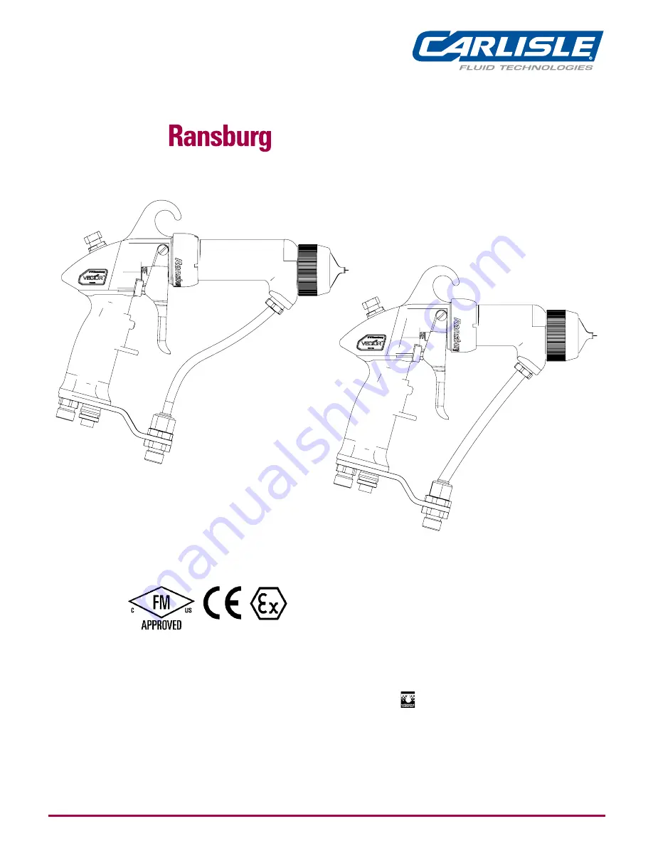
Vector

TM

 R Series 

Cascade Applicators

Model:


79500 R90 Cascade - Solventborne


79501 R70 Cascade - Solventborne


79523 R90 Cascade - Waterborne


For Use With 80131-xxx Control Unit

AH-06-01-R17  (08/2019)

1 / 79

www.carlisleft.com

EN

SERVICE MANUAL

Содержание Ransburg Vector R Series

Страница 1: ...in this manual Keep this Service Manual for future reference VectorTM R Series Cascade Applicators Model 79500 R90 Cascade Solventborne 79501 R70 Cascade Solventborne 79523 R90 Cascade Waterborne For Use With 80131 xxx Control Unit AH 06 01 R17 08 2019 1 79 www carlisleft com EN SERVICE MANUAL ...

Страница 2: ...een changed from revision AH 06 01 16 to revision AH 06 01 R17 Reasons for this change are noted under Manual Change Summary inside the back cover of this manual AH 06 01 R17 08 2019 2 79 www carlisleft com MANUAL CHANGES EN ...

Страница 3: ...e Installation 24 Low Voltage Cable 26 Filters 26 Paint Preparation 27 Spray Pattern Adjustment 28 Applicator to Target Distance 28 Fluid Nozzle Air Cap Selection Charts 28 Round Spray Performance Chart 29 OPERATION 30 34 Powering Up Control Unit 30 Setpoint Voltage 30 Lockouts 31 KV Test Jumper 33 Basic Operation 33 Fault Descriptions 34 MAINTENANCE 35 53 Suitable Solvents for Cleaning Vector R90...

Страница 4: ...50 Power Supply Electrical Specifications 63 R90 Cascade Waterborne Typical Installation 65 Waterborne Isolation System Installation Guidelines 66 Waterborne Hose Fitting Installation 66 Waterborne Fluid Delivery Components Parts List 68 Vector R90 Cascade Waterborne Model Identifications 70 Vector Air Hose Options Parts List 71 Vector Fluid Hose Options Parts List 71 Vector Applicator Cover Optio...

Страница 5: ...ncile such differences WARNING WARNING The user MUST read and be familiar with the Safety Section in this manual and the safety literature therein identified This equipment is intended to be used by trained personnel ONLY This manual MUST be read and thoroughly understood by ALL personnel who operate clean or maintain this equipment Special care should be taken to ensure that the WARNINGS and safe...

Страница 6: ...y booth ventilation must be kept at the rates required by NFPA 33 OSHA country and local codes In addition ventilation must be maintained during cleaning operations using flammable or combustible solvents Electrostatic arcing must be prevented Safe sparking distance must be maintained between the parts being coated and the applicator A distance of 1 inch for every 10KV of output voltage is require...

Страница 7: ...ertent arcing that is capable of causing fire or explosion is lost if the current overload sensitivity is not properly set Frequent power supply shutdown indicates a problem in the system which requires correction Always turn the control panel power off prior to flushing cleaning or working on spray system equipment Before turning high voltage on make sure no objects are within the safe sparking d...

Страница 8: ...aring or carrying any ungrounded metal objects When using an electrostatic handgun operators must assure contact with the handle of the applicator via conductive gloves or gloves with the palm section cut out NOTE REFER TO NFPA 33 OR SPECIFIC COUNTRY SAFETY CODES REGARDING PROPER OPERATOR GROUNDING All electrically conductive objects in the spray area with the exception of those objects required b...

Страница 9: ...ntact with the skin Follow the requirements of the Safety Data Sheet supplied by coating material manufacturer Adequate exhaust must be provided to keep the air free of accumulations of toxic materials Use a mask or respirator whenever there is a chance of inhaling sprayed materials The mask must be compatible with the material being sprayed and its concentration Equipment must be as prescribed by...

Страница 10: ...cturer s documentation 8 The certification of this equipment relies upon the following materials used in its construction If the equipment is likely to come into contact with aggressive substances then it is the responsibility of the user to take suitable precautions that prevent it from being adversely affected thus ensuring that the type of protection provided by the equipment is not compromised...

Страница 11: ...conditions for safe use apply Special conditions for safe use The Vector 79500 79501 and 79523 R Series Cascade Applicators shall only be used with associated 80131 21X Control Unit Product Marking II 2 G Ex Specific marking of explosive protection II Equipment Group hazardous area characteristics 2 Equipment Category G Type of explosive atmosphere gases vapors or mists EEx 0 24mJ The Vector 79500...

Страница 12: ...FIGURATION DWG 79946 REV B B DESIGNATIONS E DESIGNATIONS C DESIGNATIONS D DESIGNATIONS A DESIGNATIONS VECTOR R90 CASCADE SOLVENT BASE 79500 Base Model No Optional Designations ABCDE Ordering Information Only CONFIGURATION DWG 79946 REV C Return To Contents AH 06 01 R17 08 2019 12 79 www carlisleft com ATEX EN ...

Страница 13: ... 30ft PART NUMBER 79525 10 2 FOR WATERBORNE FLUID HOSE 3 16 ID X 10m 30ft PART NUMBER 79524 10 3 FOR WATERBORNE FLUID HOSE 1 4 ID X 15m 50ft PART NUMBER 79525 15 4 FOR WATERBORNE FLUID HOSE 3 16 ID X 15m 50ft PART NUMBER 79524 15 CONFIGURATION DWG 79951 REV B OPTION A DESIGNATIONS CABLE LENGTH 0 FOR NO CABLE 1 FOR 10 METER CABLE PART NUMBER 79338 10 2 FOR 15 METER CABLE PART NUMBER 79338 15 3 FOR ...

Страница 14: ...79501 ABCDE BASE MODEL NO OPTION DESIGNATIONS ORDERING INFORMATION ONLY CONFIGURATION DWG 79947 REV B VECTOR R70 CASCADE SOLVENT BASE 79501 Base Model No Optional Designations ABCDE Ordering Information Only CONFIGURATION DWG 79947 REV C Return To Contents AH 06 01 R17 08 2019 14 79 www carlisleft com ATEX EN ...

Страница 15: ... 30ft PART NUMBER 79525 10 2 FOR WATERBORNE FLUID HOSE 3 16 ID X 10m 30ft PART NUMBER 79524 10 3 FOR WATERBORNE FLUID HOSE 1 4 ID X 15m 50ft PART NUMBER 79525 15 4 FOR WATERBORNE FLUID HOSE 3 16 ID X 15m 50ft PART NUMBER 79524 15 CONFIGURATION DWG 79951 REV B OPTION A DESIGNATIONS CABLE LENGTH 0 FOR NO CABLE 1 FOR 10 METER CABLE PART NUMBER 79338 10 2 FOR 15 METER CABLE PART NUMBER 79338 15 3 FOR ...

Страница 16: ...IGURATION DWG 79951 REV B B DESIGNATIONS E DESIGNATIONS C DESIGNATIONS D DESIGNATIONS A DESIGNATIONS VECTOR R90 CASCADE WATER BASED 79523 Base Model No Optional Designations ABCDE Ordering Information Only CONFIGURATION DWG 79951 REV C Return To Contents AH 06 01 R17 08 2019 16 79 www carlisleft com ATEX EN ...

Страница 17: ...338 10 2 FOR 15 METER CABLE PART NUMBER 79338 15 3 FOR 20 METER CABLE PART NUMBER 79338 10 2 4 FOR 25 METER CABLE PART NUMBER 79338 10 1 79338 15 1 5 FOR 30 METER CABLE PART NUMBER 79338 15 2 OPTION B DESIGNATIONS TRIGGER TYPE 2 FOR TWO FINGER TRIGGER PART NUMBER 79325 02 4 FOR FOUR FINGER TRIGGER PART NUMBER 79325 04 OPTION D DESIGNATIONS SPRAY TECHNOLOGY 0 FOR STANDARD SPRAY 65V CAP 44 NOZZLE PA...

Страница 18: ...rostatic field become electrically charged The charged particles are attracted to and deposited on the target object The forces between the charged particles and the grounded target are sufficient to turn most normal overspray around and deposit it on the back surface of the target Therefore a high percentage of the coating is deposited on the target One of the many features of the Vector R90 70 a...

Страница 19: ...C maximum Current Output 100 microamperes maximum Paint Resistance 1 MW to Use Model No 76652 Test Equipment Part Sprayability Determine sprayability of part to be coated using 76652 Test Equipment See current Paint HV SCI Test Equipment service manual 79500 R90 CASCADE SOLVENTBORNE SPECIFICATIONS Environmental Physical Electrical Mechanical This reflects the maximum fluid volume the applicator ca...

Страница 20: ...C maximum Current Output 90 microamperes maximum Paint Resistance 1 MW to Use Model No 76652 Test Equipment Part Sprayability Determine sprayability of part to be coated using 76652 Test Equipment See current Paint HV SCI Test Equipment service manual 79501 R70 CASCADE SOLVENTBORNE SPECIFICATIONS Environmental Physical Electrical Mechanical This reflects the maximum fluid volume the applicator can...

Страница 21: ...Air Adjust 5 2 Finger 4 Finger Trigger No Description 6 Adjustable Trigger Shelf 7 Fluid Hose Connection 8 Low Voltage Cable Connection 9 Air Inlet Connection 10 kV Setpoint Switch Microamp Display R90 70 CASCADE SOLVENTBORNE ELECTROSTATIC SPRAY APPLICATOR FEATURES Return To Contents AH 06 01 R17 08 2019 21 79 www carlisleft com INTRODUCTION EN ...

Страница 22: ...hes Weight 3 4 kg 7 5 lbs Physical Supply Air 6 9 bar 100 psig maximum Pneumatic 80131 XXX 1 USA Canada 2 Europe 3 China Plug Styles 110 120 VAC 220 240 VAC 110 120 VAC 220 240 VAC 80131 211 80131 212 213 80131 311 80131 312 313 65 kV DC 65 kV DC 85 kV DC 85 kV DC Voltage Designation Maximum Output 9060 Part 79501 XXXXX 79500 XXXXX 79523 XXXXX 80131 21X 80131 31X 80131 51X For Use With 9060 Part C...

Страница 23: ...Figure 2 80131 XXX Cascade Control Unit Features μ μ Return To Contents AH 06 01 R17 08 2019 23 79 www carlisleft com INTRODUCTION EN ...

Страница 24: ...ocal building and fire codes and ordinances as well as NFPA OSHA and all related country safety codes prior to installing operating and or servicing this eqiupment The fluid lines and fluid sources MUST be isolated from ground for waterbase applications Personnel MUST be GROUNDED to prevent a shock or spark during electrostatic operation Install and route the hoses and cable so they are NOT expose...

Страница 25: ...ir Supply Line No Description No Description 8 Fluid Supply Grounded 9 Fluid Regulator 10 Air Line 11 Low Voltage Cable 12 Fluid Line 13 Target Earth or Building Ground 14 9060 Ground Separate Earth or Building Ground TYPICAL SOLVENTBORNE INSTALLATION FEATURES 7 6 5 4 10 2 1 14 10 11 3 13 12 9 8 5 4 R 1 MEGOHM Return To Contents AH 06 01 R17 08 2019 25 79 www carlisleft com INSTALLATION EN ...

Страница 26: ...ust be prevented by grounding the paint line at the applicator handle Verifythattheapplicatorhandleisactuallyground ed before operating it This is done with a fully connected and operational system by placing one lead of an ohmmeter to the handle and the other to the building electrical ground cold water pipe building structure steel etc This reading should be essentially zero If a greater reading...

Страница 27: ...PSM M When installing the air hose use a wrench to hold the air inlet fitting on the Vector and tighten the air hose fitting enough to prevent any air leaks Any user installed fluid hose used must be rated for 100 psig 6 9 bar working pressure minimum When securing the air hose fluid hose and low voltage cable together take care not to use items such as wire or anything that might cut into the hos...

Страница 28: ...hertransferefficiencywillbeachieved at the closer target distance Trigger the applicator fully to operate Orifice ID Fluid Nozzle Part Nozzle Material FLUID NOZZLE SELECTION STD SPRAY CHART 79377 44 1 4mm 055 inch Standard Wear 79377 144 1 4mm 055 inch Extended Wear 79377 45 1 8mm 070 inch Standard Wear 79377 145 1 8mm 070 inch Extended Wear 79377 46 1 0mm 042 inch Standard Wear 79377 146 1 0mm 04...

Страница 29: ...7 45 79522 245 Fluid Nozzle Part Fluid Delivery ml min Orifice ID in m 070 1 8 070 1 8 070 1 8 300 300 300 Spray Type Air Spray Air Spray LVMP Air Consumption SCFM SLPM 18 510 18 510 8 3 234 Air Pressure psi bar 22 1 5 37 2 6 30 2 1 Air Cap 79374 65 79374 98 79374 122 Pattern Size inches 15 1 2 17 1 2 12 1 2 Pressure Reducer Black Black Green Applicators Vector 79959 00 Fluid Nozzle Part Retaining...

Страница 30: ... level in the µAdisplay for 2 3 seconds Figure 4 Control Unit Start Up Display Description Applicator Type 1 5 85 kV Cascade 65 kV Cascade Setting and Changing the Setpoint at the Control Unit From the factory Preset 1 is full minus 20 kV Preset 2 is full kV minus 10 and Preset 3 is full kV For 79500 79523 full kV is 85 kV For 79501 full kV is 65 kV At the control unit with the applicator not trig...

Страница 31: ... If there are 2 green lights lit setpoint 1 is active If 2 green lights and 2 yellow lights are lit setpoint 2 is active If all lights are lit 2 green lights 2 yellow lights and 2 red lights setpoint 3 is active kV to the applicator can be turned off by pressing the ap plicator kV button in for 2 3 seconds This can be done whether the applicator is triggered or not and is useful if the kV needs to...

Страница 32: ... 10 Jumper Location Applicator Switch Lockout 1 Turn AC power off and access the interior of the control unit 2 Place the jumper across the two 2 pins at location 15 on the main PC board see Figure 10 3 Close the control unit and turn AC power back on It will now be no longer possible to change setpoints or turn kV off at the applicator Overload Activation The overload circuit may be activated for...

Страница 33: ...d transfer efficiency The display at the rear of the applicator also doubles as a microamp bar graph meter when high voltage is on see Figure 13 Its function is similar to that of the control unit bar graph display KV TEST JUMPER To assist in testing and troubleshooting a jumper J8 has been added to the main PC board By covering shorting both terminals of this jumper the high voltage to the spray ...

Страница 34: ...t 2 and reset buttons at the same time will show the number of hours on the non re settable register Local Remote TheVectorproductlineisdesignedcurrentlyforapplicators only The local remote high voltage control switch should be set to local for all Vector applicator applications Figure 15 High Voltage Control Switch FAULT DESCRIPTIONS For in depth troubleshooting information on the 9060 refer to C...

Страница 35: ...m on the surface of the applicator that will effect efficiency of the applicator and cause damage to the components SUITABLE SOLVENTS FOR CLEANING VECTOR R90 70 APPLICATORS Whencleaningtheapplicator asuitablesolventforcleaning depends on the part s of the applicator to be cleaned and the material that needs to be removed Ransburg recom mends that all exterior cleaning be done with non polar solven...

Страница 36: ...g any atomizer maintenance procedure see Applicator Assembly Cleaning Procedure in the Maintenance section The applicator barrel MUST be tilted front down to remove the fluid nozzle Failure to do so may allow paint to enter the air passages thereby reducing airflow and damaging the applicator barrel cascade Applicatorsmaybeflushedinlieu of tilting However they must be either flushed or tilted down...

Страница 37: ...ed see Flushing Proce dures in the Maintenance section Weekly Check the entire system for damage leaks and paint accumulation Clean the atomizer assembly APPLICATOR ASSEMBLY CLEANING PROCEDURE Routine Cleaning Equipment Needed An appropriate solvent A solvent safety container grounded A small soft bristled brush The Ransburg special multi purpose wrench 19749 00 Shutdown or at end of each shift 1 ...

Страница 38: ...Y Only approved applicator covers should be used Any broken or damaged components should be replaced Any damage to the applicator may result in UNSAFE operating conditions 5 Clean the applicator and associated parts with a soft brush and suitable solvent Metal tools and wire brushes must NEVER be used NEVER use a cleaning tool that is harder than the plastic parts If a deposit cannot be removed wi...

Страница 39: ...Strength 7969 10 Plastic or Wood Dowel Rod 5 16 Diameter CAUTION TO REMOVE THE APPLICATOR FROM THE WORK SITE ALWAYS remove the applicator from the work site for service or repair DO NOT use any silicone lubricants in order to avoid paint defects WARNING Solventborne Applicators 1 Flush the applicator Refer to Flushing Procedures in the Maintenance section 2 With a wrench loosen and unscrew the flu...

Страница 40: ...he Maintenance section 2 Tilt the applicator forward and pull the trigger to make sure that all fluid in the applicator is drained out Figure 18 Removal of Fluid Nozzle CAUTION The applicator barrel MUST be tilted front down to remove the fluid nozzle Failure to do so may allow paint to enter the air passages thereby reducing air flow and damaging the applicator barrel Applicators may be flushed i...

Страница 41: ...rpose wrench with 3 8 square Torque to 40 45 lbs in 4 5 5 1 Nm An alternate method if no torque wrench is available is to hand tighten then tighten an additional 1 16 to 1 8 turn in the clockwise direction 4 Install the air cap and retaining ring onto the applicator refer to Air Cap Reinstall in the Maintenance section Figure 20 Reinstalling Fluid Nozzle C W 3 5 4 0 L B S IN 3 9 4 5 N M NOTE DO NO...

Страница 42: ...n a weekly basis or any time it is removed from the applicator Figure 21 Testing Resistive Electrode To Test 1 Install the needle electrode onto the front end of an availableneedleshaft Besurethattheneedle electrode is completely seated for proper contact between the metal shaft and the threaded insert of the needle electrode 2 Using a VOM meter that will read 15 megohms accurately connect the fir...

Страница 43: ...end of retaining ring over the captive ridge and spiral it off the end of the barrel Then the retaining nut can be removed Use care in removing the retaining ring If it is spread too much it could break Figure 23 Removal of Needle Shaft NOTE 3 Hold the barrel in one hand and with a firm pull remove the needle shaft assembly from the packing chamber of the barrel The trigger adjustment nut can be r...

Страница 44: ...remove the packing nut spacer rear seal retainer sub assembly and packing tube from the rear of the needle shaft The spring loaded u cup and o ring can now be re moved from the rear seal retainer Cleaning and Inspection 1 Clean the packing chamber of the barrel with a suitable solvent and a soft bristle bottle brush DO NOT sub merge or soak the barrel in solvent If the chamber has dry paint in it ...

Страница 45: ... tube and to the external o ring on the cartridge seal FAILURE to coat the needle shaft assembly MAY CAUSE lower electrical output of the applicator 1 Place conductive female chevron adapter onto the front of shaft with the concave side toward the front 2 Screw the four 4 chevron seals onto shaft concave sides forward Be generous with the dielectric grease when ap plying it to the packing tube and...

Страница 46: ...ting thread in the barrel and screw it into place by hand approximately 3 turns 16 Pull the needle shaft rearward as far as it will go 17 Install the fluid nozzle air cap and retaining nut refer to Air Cap and Fluid Nozzle in the Maintenance section 18 Tighten the packing nut using the spanner tool on the special multi purpose wrench until a firm resistance is felt on the needle shaft while recipr...

Страница 47: ...ecess 6 While holding the barrel in place screw the retaining nut onto the handle by hand and then tighten using the special multi purpose wrench Torque the retaining ring to 8 10 lbs ft or after hand tightening torque an additional 1 6 to 1 8 turn using the special multi purpose wrench Figure 30 Barrel to Handle Assembly 7 Check the spacing between the back of the spring retainer and the handle I...

Страница 48: ... Nut 2 Seal opening toward applicator rear 3 Air Valve 4 Air Valve Return Spring 5 Solvent Proof O Ring 6 Air Valve Retaining Cap 1 Hook 2 Hook Gasket 3 Plug Assembly Set Screw loosen 4 Plug Assembly pull straight out Description Item AIR VALVE REMOVAL Description Item AIR VALVE AND REAR COVER REMOVAL HANDLE PLUG ASSEMBLY Removal 1 The following procedures must be performed prior to removing the h...

Страница 49: ...he fluid bracket over the air fitting then install the o ring over the air fitting Tighten the air fitting in a clockwise direction Figure 37 Hook Insertion Into Handle Figure 34 Fluid Bracket Removal 6 Remove the air inlet fitting and the fluid bracket from the base of the applicator 1 Fluid Bracket 2 Air Inlet Solvent Proof O Ring 3 Air Inlet Fitting 7 Remove the trigger shelf by removing the se...

Страница 50: ...irection 7 Insert the barrel gasket back into the handle 8 Insert the plug assembly into the base of the handle Align the raised portion into the mating handle recess Figure 39 Location of Handle Low Voltage Plug Recess 4 Push the hook gasket into the groove of the hook Apply a light coat of dielectric grease LSCH0009 to the hook gasket exterior and slide the hook into position Return To Contents ...

Страница 51: ...ty air cap Ensure proper fluid nozzle air nozzle pressure reducer combinations see Fluid Nozzle Tables in the Installation section Replace Air passages in applicator or air line clogged Inadequate air source Paint in air passage Blow out Increase pressure flow capacity Clean and blow out Air Fluid Clogged or faulty fluid nozzle Clogged passages in applicator fluid tube or fluid line Insufficient n...

Страница 52: ...ection Clean and lubricate or replace Cartridge seal assembly and or needle electrode shaft defective Fluid At rear of barrel Fluid Slight leak at nozzle when trigger is released Nozzle not secure Air valve closing before fluid valve Tighten Adjust needle shaft electrode travel Fluid Constant at nozzle Worn or damaged fluid nozzle Worn or damaged needle electrode Loose fluid nozzle Needle electrod...

Страница 53: ...ulty flow switch Replace fuse Check power supply Check air regulator Check applicator trigger Check applictor switch Check conductivity of paint Replace flow switch Improper or No High Voltage Cont Isolation System Grounded Out Failed fluid hose Insolation stand or charged equipment too close to ground Replace fluid hose Provide adequate ground distance Return To Contents AH 06 01 R17 08 2019 53 7...

Страница 54: ... Solventborne Applicator Breakdown 31 45 46 37 36 40 38 39 7 5 10 1 9 8 13 2 3 4 30 27 29 28 34 33 17 35 43 42 31 44 41 18 11 12 26 25 23 19 22 24 21 20 15 14 Return To Contents AH 06 01 R17 08 2019 54 79 www carlisleft com PARTS IDENTIFICATION EN ...

Страница 55: ...85 00 O Ring Solvent Resistant 1 16 17 79460 03 Assembly Plug 1 18 79001 08 O Ring Solvent Proof 2 19 79001 07 O Ring Solvent Proof 2 20 79476 00 Handle Assembly 1 21 79445 10 Fan Air Adjust Assembly 1 22 79001 16 O Ring Solvent Proof 1 23 17130 00 Spring Return 1 24 79001 31 O Ring Solvent Proof 1 25 79453 00 Cap Retaining Air Valve 1 26 79310 00 Air Valve Assembly 1 27 78635 00 Nut Retaining Air...

Страница 56: ... Support 1 42 Table C C1 Fitting Fluid Straight Offset Bracket 1 43 Table C C3 Nut Hex 1 44 18847 01 Fitting Air Inlet 1 4 NPSM M Std 1 18847 00 Fitting Air Inlet 3 8 NPSM M Optional 1 45 Table A A2 Cable Low Voltage Vector Table A A1 46 19749 00 Special Applicator Wrench 1 47 72315 00 Conductive Ferrule 1 48 6241 06 Fitting Fluid 1 49 7787 03 Swivel Fitting 1 Return To Contents AH 06 01 R17 08 20...

Страница 57: ...igger 0 Standard Spray 65kV Air Cap 1 4mm Fluid Nozzle 44 1 Standard Spray 65kV Air Cap 1 8mm Fluid Nozzle 45 2 Trans Tech 122V Air Cap 1 8mm Fluid Nozzle 245 3 Round Spray 0 Applicator Only 1 Domestic Sales Complete W Power Supply 110 120 2 Export Sales Complete W Power Supply 240V 50 60Hz 79500 79501 A B C D E No Cable 10m 15m 20m 25m 30m 79338 10 79338 15 79338 10 79338 10 79338 15 79338 15 A2 ...

Страница 58: ...BLE E CONTROL UNIT 1 2 3 4 5 6 7 Offset Bracket 093 ID Fluid Tube 45 Bracket 093 ID Fluid Tube Offset Bracket SS 093 ID Fluid Tube Offset Bracket 250 ID Fluid Tube 45 Bracket 250 ID Fluid Tube Offset Bracket SS 250 ID Fluid Tube Offset Bracket 125 ID Coiled Fluid Tube 70399 00 70442 00 70399 00 70399 00 70442 00 70399 00 79650 00 C1 Description C Dash 79438 00 79439 00 79438 01 79438 00 79439 00 7...

Страница 59: ...5 Cup Seal Spring Loaded 1 10 78630 00 Spacer Seal 1 11 17390 04 Washer Beville Spring 6 12 78632 00 Nut Locking Trigger Adjustment 1 13 78631 00 Nut Packing 1 14 78633 00 Spring Retainer Needle Shaft 1 15 78824 00 Spring 1 16 SI 07 03 Service Instruction 1 Item R90 79599 01 AND R70 79599 02 CASCADE NEEDLE SHAFT STANDARD 2K PACKINGS PARTS LIST Figure 41 Part Description Qty Figure 41 R90 79599 01 ...

Страница 60: ... 02 Tube Packing R70 1 5 78629 00 Retainer Needle Seal Rear 1 6 79001 06 O Ring Solvent Proof 1 7 78630 00 Spacer Seal 1 8 10051 05 Cup Seal Spring Loaded 1 9 78631 00 Nut Packing 1 10 78632 00 Nut Locking Trigger Adjustment 1 11 78633 00 Spring Retainer Needle Shaft 1 12 78636 00 Spring 1 Item R90 78628 11 AND R70 78628 12 CASCADE NEEDLE SHAFT OPTIONAL PACKINGS PARTS LIST Figure 42 Part Descripti...

Страница 61: ...NING Typical installations to spray non flammable conductive materials waterborne materials must not be used to handle flammable materi als solvent based materials Return To Contents AH 06 01 R17 08 2019 61 79 www carlisleft com PARTS IDENTIFICATION EN ...

Страница 62: ...Cascade Waterborne Electrostatic Spray Applicator Features 7 Waterborne Hose 8 Low Voltage Cable Connection 9 Air Hose Connection 10 kV Setpoint Switch Microamp 11Display 11 Waterborne Source Connection R90 CASCADE WATERBORNE ELECTROSTATIC SPRAY APPLICATOR FEATURES Figure 43 Return To Contents AH 06 01 R17 08 2019 62 79 www carlisleft com PARTS IDENTIFICATION EN ...

Страница 63: ...9377 45 Operating Voltage 85 kV DC maximum Current Output 100 microamperes maximum Part Sprayability Determine sprayability of part to be coated using 76652 Test Equipment See current Paint HV SCI Test Equipment service manual 79523 R90 CASCADE WATERBORNE SPECIFICATIONS Environmental Physical Electrical Mechanical 79513 1XX 9050 POWER SUPPLY ELECTRICAL SPECIFICATIONS Input Voltage 100 240 VAC Curr...

Страница 64: ...ltage Designation Maximum Output 9050 Part 79523 XXXXX 79513 12X For Use With Applicator Combinations 9050 Part CONTROL UNIT APPLICATOR COMBINATIONS CONTROL UNIT INPUTS OUTPUTS Return To Contents AH 06 01 R17 08 2019 64 79 www carlisleft com PARTS IDENTIFICATION EN ...

Страница 65: ...upply Grounded No Description R 1 ME G OH M R90 CASCADE WATERBORNE TYPICAL INSTALLATION 9 Fluid Regulator 10 Air Line 11 Low Voltage Cable 12 Fluid Valve 13 Isolated Fluid System Protection required from human contact 14 Target Earth or Building Ground 15 9060 Ground Separate Earth or Building Ground 11 10 3 14 12 9 8 13 5 4 6 7 5 4 10 2 1 15 Return To Contents AH 06 01 R17 08 2019 65 79 www carli...

Страница 66: ...terborne Ransburg supplies the waterborne fluid hose factory pre assembled to the applicator unit Standard hose lengths are 10m 15m and 25m To modify the hose length use the following procedures All adjustments must be made at the supply end of the system 1 Remove the male connector and swivel fitting from the end of the fluid hose by turning the nut of the male con nector counter clockwise while ...

Страница 67: ... score mark and peel it away from the core fluid hose Then remove the sheath completely by tearing along the radial score mark 6 Roll the inner sheath back over itself until it touches the outer jacket 7 Cut approximately 1 4 inch of inner sheath off Special care must be taken when removing the sheathing from the fluid hose Make sure all tools are very sharp and only score the surface of the sheat...

Страница 68: ...Figure 45 Waterborne Fluid Delivery Components Return To Contents AH 06 01 R17 08 2019 68 79 www carlisleft com PARTS IDENTIFICATION EN ...

Страница 69: ...ut Hex 1 64 79438 00 Bracket Support Offset Std 1 79438 01 Bracket Support Offset Stainless Steel Optional 1 65 72315 00 Conductive Ferrule 1 66 3587 02 Nut 3 8 1 67 79385 00 Nut Connector Hose 1 68 EMF 203 05 Tube Ferrule Front 3 8 1 69 EMF 202 05 Tube Ferrule Back 3 8 1 70 6241 06 Fitting Fluid 1 71 7787 03 Swivel Fitting 1 Item WATERBORNE FLUID DELIVERY COMPONENTS PARTS LIST Figure 45 Part Desc...

Страница 70: ... x 10m 2 Waterborne Fluid Hose 3 16 ID x 10m 3 Waterborne Fluid Hose 1 4 ID x 15m 4 Waterborne Fluid Hose 3 16 ID x 15m 0 Standard Spray 65kV Air Cap 1 4mm Fluid Nozzle 44 1 Standard Spray 65kV Air Cap 1 8mm Fluid Nozzle 45 2 Trans Tech 122V Air Cap 1 8mm Fluid Nozzle 245 3 Round Spray 0 Applicator Only 1 Domestic Sales Complete W Power Supply 110 120 2 Export Sales Complete W Power Supply 240V 50...

Страница 71: ...onal Fluid Hose 79548 10 Fluid Hose Assembly 10m 33 79548 15 Fluid Hose Assembly 15m 49 79548 20 Fluid Hose Assembly 20m 66 79548 31 Fluid Hose Assembly 30m 99 1 14599 00 Nut 1 2 7623 00 Union Stem 1 3 7617 00 Ferrule 1 4 77031 XX Bulk Hose Fluid XX Item VECTOR FLUID HOSE OPTIONS PARTS LIST Figure 47 Part Description Qty 2 1 1 2 3 4 VECTOR AIR HOSE OPTIONS PARTS LIST Figure 46 Return To Contents A...

Страница 72: ...ONS PARTS LIST Part Description Qty Figure 48 Applicator Cover 1 79959 00 Fluid Nozzle Assembly 1 2 79962 00 Air Cap Swirl 1 Item VECTOR SWIRL NOZZLE OPTIONS PARTS LIST Part Description Qty Figure 49 Swirl Nozzle 1 2 1 Return To Contents AH 06 01 R17 08 2019 72 79 www carlisleft com PARTS IDENTIFICATION EN ...

Страница 73: ...t with highly conductive materials down to 1 megohm resistance If higher fluid flows are required the larger diameter tube either 125 inch or 250 inch may be used but depending on material conductivity the current draw during the spray operation may increase 36 Figure 51 Low Voltage Cable Description Part 79338 01 LOW VOLTAGE CABLE OPTION Qty Low Voltage Cable 1 Meter 1 Return To Contents AH 06 01...

Страница 74: ...RTS LIST Part Description Qty 79374 65 Standard Air Spray Air Cap 79374 122 Trans Tech Air Spray Air Cap 79377 XX Standard Air Spray Fluid Nozzle 79552 XXX Trans Tech Air Spray Fluid Nozzle 74963 05 Standard Air Spray Restrictor 74963 06 Trans Tech Air Spray Restrictor PARTS COMPARISON Standard Air Spray Nozzles have a number between 44 and 148 Trans Tech Air Spray Nozzles have a number between 24...

Страница 75: ...r green and chosen Fluid Nozzle Kit 79555 replaces parts 74963 05 Restrictor 79377 45 Fluid Nozzle 79374 65 Air Cap NOTE For additional information on solvent Viscosities and Conversion refer to Technical Manual IL 307 www ransburg com Part No 77582 00 77581 00 Description Nozzle Drain Flush Box REA90 to REA70 Adapter Flush Box 79555 TRANS TECH CONVERSION KITS AVAILABLE ACCESSORIES FOR ECON FLUSH ...

Страница 76: ...olvent Proof 4 79001 09 O Ring Solvent Proof 6 79001 16 O Ring Solvent Proof 6 79001 31 O Ring Solvent Proof 2 79310 00 Air Valve Assembly 2 79322 00 Applicator Hook 1 79325 02 Trigger 2 Finger 1 79338 01 Low Voltage Cable 1m Accessory 79338 10 Low Voltage Cable 10m 1 79338 15 Low Voltage Cable 15m Accessory 79373 00 Barrel Retaining Nut 1 79374 65 Air Cap V65 3 79374 98 Air Cap V98 1 79377 44 Flu...

Страница 77: ...ry 79560 00 Trigger Stop Assembly 1 79599 01 Needle Shaft Assembly R90 2k Packings 1 79599 02 Needle Shaft Assembly R70 2k Packings 1 9704 16 Fluid Tube R70 Standard 1 Fluid Tube R90 Standard 2 Ft A11745 00 K5 Cable Boot Accessory EMF 202 05 Ferrule Back 2 EMF 203 05 Ferrule Front 2 LSOR0005 17 O Ring PTFE Encapsulated 6 Power Supply Components 79390 20 PC Board R70 Cascade 1 79390 22 PC Board R90...

Страница 78: ...ces AH 06 01 16 with the folowing changes 1 Update to latest manual format All 2 Change page head to new verbage 10 3 Change text in bullet point number two under To Test 42 Page s Return To Contents AH 06 01 R17 08 2019 78 79 www carlisleft com MANUAL CHANGES EN ...

Страница 79: ...es is a global leader in innovative finishing technologies Carlisle Fluid Technologies reserves the right to modify equipment specifications without prior notice DeVilbiss Ransburg MS BGK and Binks are registered trademarks of Carlisle Fluid Technologies Inc 2019 Carlisle Fluid Technologies Inc All rights reserved Tel 44 0 1202 571 111 Fax 44 0 1202 573 488 Tel 8621 3373 0108 Fax 8621 3373 0308 Te...

Отзывы: