Caple C875I, Instruction Manual
The Caple C875I Instruction Manual is available for free download on our website. This comprehensive manual provides step-by-step instructions and valuable information for using your Caple C875I device. Get the most out of your product by easily accessing the manual from manualshive.com.
Share
Download


Reviews:
No comments
Related manuals for C875I

GH 87B-GH 87G
Brand: Zanussi Pages: 7

EB1465
Brand: Zanussi Pages: 12

T1.K40X2
Brand: NEFF Pages: 24

VP230120
Brand: Gaggenau Pages: 16

226317 Q21
Brand: Teka Pages: 113
C61R1ABMAL
Brand: Samsung Pages: 34
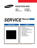
C61R1AAMST
Brand: Samsung Pages: 41
C61R2AEE
Brand: Samsung Pages: 70
C61R1AAMST
Brand: Samsung Pages: 352

TIH3501S
Brand: tomado Pages: 88

EIT-6328 R
Brand: Edesa Pages: 64

B100037
Brand: CONTINENTAL EDISON Pages: 40

CETI3Z1B
Brand: CONTINENTAL EDISON Pages: 44

KM9111 EN S
Brand: Respekta Pages: 21

KM 9111 EN
Brand: Respekta Pages: 31

5059340445847
Brand: Kingfisher Pages: 151

Style
Brand: Rosle Pages: 44

LAM1500
Brand: Lamona Pages: 24


