Canon CR-S700R, Instruction Manual
The Canon CR-S700R Instruction Manual is a comprehensive guide that assists users in optimizing the features and functionalities of this advanced product. Available for free download from our website, this user-friendly manual provides step-by-step instructions and valuable tips to ensure seamless operation and maximum utility of your Canon CR-S700R device.
Share
Download


Reviews:
No comments
Related manuals for CR-S700R

Smart C1640W
Brand: GE Pages: 76

POWER series E1486TW
Brand: GE Pages: 93

A Series A1456W
Brand: GE Pages: 85

Whatman Mini-UniPrep G2
Brand: GE Pages: 106

J1456W
Brand: GE Pages: 86

E1450W
Brand: GE Pages: 85

E1450W
Brand: GE Pages: 85

E1250TW
Brand: GE Pages: 2

E1050TW
Brand: GE Pages: 2

C1440W
Brand: GE Pages: 76
R50
Brand: Kaiser Baas Pages: 2

P-Series
Brand: Datalogic Pages: 56

A20
Brand: Datalogic Pages: 4
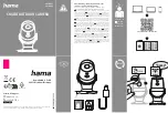
00176645
Brand: Hama Pages: 2

V-LUX
Brand: Leica Pages: 337

Infinity SuperZoom 330
Brand: Olympus Pages: 66

PHD5N1
Brand: EchoMaster Pro Pages: 4
XP350 magic
Brand: x-pointer Pages: 13


