background image


89 TLC 

Tannins 

Reduction System 

O

w

n

e

rs

 M

a

n

u

a

REVISION # 

REVISION DATE  May 4,2015 
54616 

1.  Read all instructions carefully before operation. 
2.  Avoid pinched o-rings during installation by applying (provided with install kit) NSF certified 

lubricant to all seals. 

3.  This system is not intended for treating water that is microbiologically unsafe or of unknown 

quality without adequate disinfection before or after the system. 

Canadian Head Office


655 Park St.


Regina, SK S4N 5N1


U.S. Head Office 

8437 10th Avenue North 
Golden Valley, MN 55427 

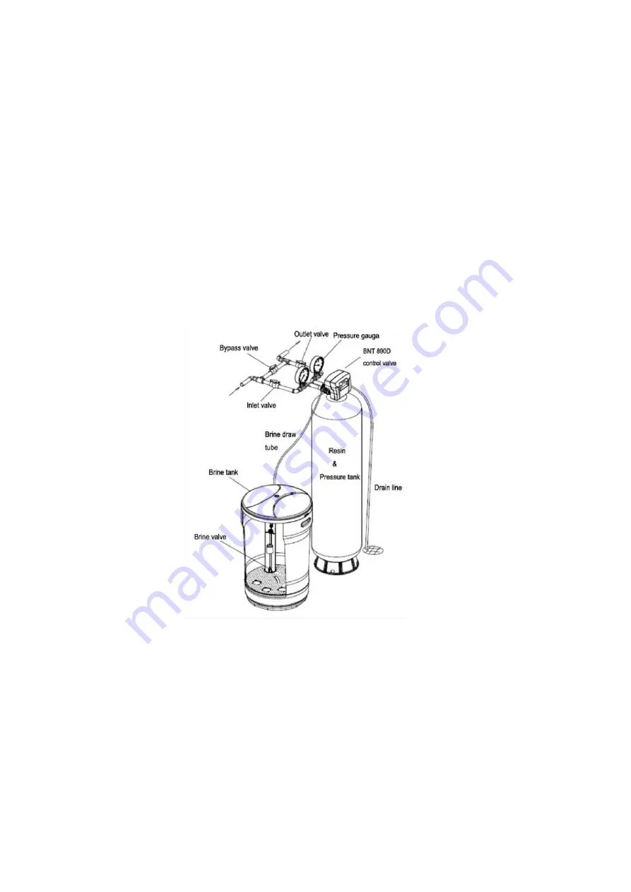
IMPORTANT—PLEASE REFER TO THE PICTURE BELOW ON INLET/OUTLET SIDE OF THE 
VALVE  

Summary of Contents for Tannins 89 TLC

Page 1: ...ith install kit NSF certified lubricant to all seals 3 This system is not intended for treating water that is microbiologically unsafe or of unknown quality without adequate disinfection before or aft...

Page 2: ...treating water that is microbio logically unsafe or of unknown quality without adequate disinfection before or after the system For your safety the information in this manual must be followed to mini...

Page 3: ...ces Use only lead free solder and flux for all sweat solder connections as required by state and federal codes Maximum allowable inlet water pressure is 125 psi If daytime pressure is over 80 psi nigh...

Page 4: ...rate may affect capacity and efficiency performance The manufacturer reserves the right to make product improvements which may deviate from the specifications and descriptions stated herein without ob...

Page 5: ...not covered by the war ranty Put the softener in a place water damage is least likely to occur if a leak develops The manufacturer will not repair or pay for water damage A 120 volt electric outlet to...

Page 6: ...his could cause damage to the valve 5 Connect the drain hose 10 ft included to the valve and secure it with a hose clamp also included Run the drain hose to the nearest laundry tub or drain pipe This...

Page 7: ...7 Installation...

Page 8: ...e O ring is coated with grease 2 Connection method of inlet and outlet connector same as the above make sure to connect according to the direction of arrow seeing from the top view 3 It is also recomm...

Page 9: ...en close the bypass valve slowly open the inlet valve the raw water filling the tank and empty the air of the system open the valve more until the backwash water is clean 5 Press any key to advance th...

Page 10: ...s the Flow Rate Date Time Of Day Remaining Volume and Total Volume The display will alternate between the main page and the dealer information page PROGRAM LEVEL USER ACCESS MAIN MENU II These setting...

Page 11: ...E Time of day is for normal operation of system and the scheduling of the regeneration time The date is used in a diagnostic function to track the last time the sys tem regenerated HARDNESS This value...

Page 12: ...FLOW valve backwash brine slow rinse fast rinse service refill The regeneration steps of UP FLOW valve brine slow rinse backwash fast rinse service refill Set the Down Flow valve as an example when th...

Page 13: ...Rinse the screen will display Press any key will stop fast rinse and the valve will advance to the next regeneration process Refill the screen will display Press any key will stop service refill and t...

Page 14: ...ear 1 8 Connect screw 1 9 85HE main gear 1 10 Brine gear screw 1 11 Locating wheel assembly three options Down flow wheel Up flow wheel Filter wheel 1 12 85HE brine gear 1 13 Micro switch screws 2 14...

Page 15: ...No Part description Qty No Part description Qty 1 Big O ring of Adaptor coupling 2 6 89 secure clip 2 2 Adaptor coupling of 89 control valve 2 7 89 valve connector 1 3 Small O ring of adaptor coupling...

Page 16: ...assembly optional 1S 2S 3S 4S 1 3 4 5 6 1 4 Drain elbow O ring 1 5 Drain elbow 1 2 3 4 1 6 Brine valve injector stem assembly 1 7 Spacer and seal assembly 1 8 Three options of piston Down flow piston...

Page 17: ...rine line adaptor assem bly optional BLFC 0 7gpm BLFC 0 95gpm 1 16 Injector assembly optional grey purple red white blue yellow 1 17 Injector cover O ring 1 18 Injector cover 1 19 Injector cover screw...

Page 18: ...ia to form or grow However during shipping storage installing and operating bacteria could get into the softener For this reason sanitizing as follows is suggested when installing Sani System Liquid S...

Page 19: ...ions described in the gen eral conditions of this warranty General Conditions Damage to any part of this water conditioner as a result of misuse misapplication neglect alteration accident installation...

Page 20: ...20...

Reviews: