background image

M a n u a l

OPTOSPLIT II


BYPASS

This guide details initial set up and installation of your OptoSplit II Bypass (BP) image splitter. Each unit is serial numbered, 
calibrated and QC’d prior to delivery, therefore minimal setup is required providing you are familiar with the key controls. 

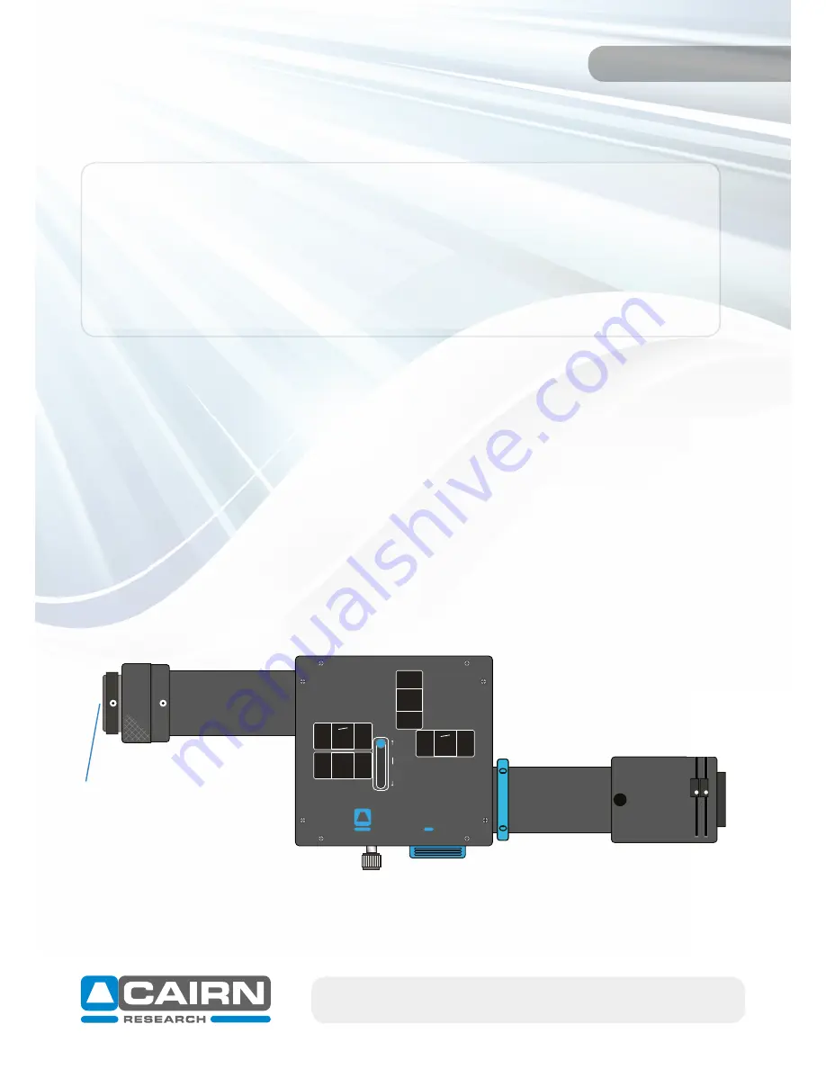
For the purpose of this manual, all words in 

bold blue

 refer to parts labelled in diagrams throughout this document.

A supplementary Troubleshooting Guide is also available to address frequently asked questions during OptoSplit operation.

Please do not hesitate to contact us if you have any questions or issues during installation or operation 
(

[email protected]

)

.

1)   Mounting to your microscope

It is best practice to firstly ensure you have optimised your microscope light source in the absence of the 

OptoSplit, with the camera mounted directly on the c-mount. Many technical queries are raised relating to 

uneven illumination, which is often not introduced by the image splitter. Once both your transmitted and 

fluorescent light source have been correctly aligned and focussed, the OptoSplit can be mounted on a 1x 

c-mount; for deviations from this, please contact us for advice.

1.1)   Correct camera orientation

The OptoSplit 

output port 

connects to your camera c-mount via a 

camera mounting thread

. The silver 

knurled section on the output port can be rotated to secure the camera, whilst also ensuring any cables 

connected do not get tangled. 

The OptoSplit 

input port

 then connects to your microscope c-mount.

email:  [email protected]   [email protected] 

+44(0)1795 590140   www.cairn-research.co.uk


For correct alignment of the two emission channels, the orientation of the camera once attached to the 

OptoSplit II BP unit is important. Always ensure the top of your camera lies parallel with the top of the 

OptoSplit. If fitting onto an upright microscope, this camera orientation remains the same.

BY

PASS


SPLIT


OPTOSPLIT

cairn-research.co.uk

Bypass

Input port

Camera mounting thread

Output port

Summary of Contents for OPTOSPLIT II BYPASS

Page 1: ...uneven illumination which is often not introduced by the image splitter Once both your transmitted and fluorescent light source have been correctly aligned and focussed the OptoSplit can be mounted o...

Page 2: ...OptoSplit using the two screws provided 2 Screw the support legs to the end of the bar 3 The height can be adjusted on each support leg we recommend a spirit level is used for final adjustment 2 Key...

Page 3: ...arch co uk 2 1 OptoSplit panels B Left side panel A Top Panel BYPASS SPLIT OPTOSPLIT cairn research co uk Bypass Bypass split lever XY controls for Bypass image Split control Rectangular aperture adju...

Page 4: ...d to ensure the Bypass image is projected onto the centre of the camera sensor It s best practise to ensure this is carried out prior to performing dual channel imaging but this adjustment can be chec...

Page 5: ...door cover 3 Adjust the two rectangular aperture adjusters one horizontal the other vertical to create a single rectangular region of interest visible on your camera 4 Ensure the image is square with...

Page 6: ...imaging software is useful as a reference tool to ensure the image is centred and square 4 Obtaining a split image The predominant operating mode of two identical images projected onto each half of y...

Page 7: ...nd horizontally using the provided 1 5mm allen key on the H V controls on the magnetic door cover Once you are aware which channel is which turn your attention to the transmitted image and position th...

Page 8: ...l ensure maximal field of view is projected onto each half of your camera sensor Vignetting may be present once split mode has been optimised This is characterised by one image appearing darker on one...

Page 9: ...end the Chroma Ultra Flat UF 2 2mm thick dichroic mirror range The Cairn Filter Cube accepts dichroic mirrors of the following size 26mm x 38mm x 2mm Other dichroic mirrors will fit but may not be opt...

Page 10: ...3 Remove the blank cover for the auxiliary drop in position reflected path Note the blank hold ers will have no angled thread indictor and act as a protector for this pocket 4 Insert the rotating pola...

Page 11: ...ugins folder in your root MicroManager folder on the C drive A MicroManager plugin for use with version 2 0 is also currently in development Keep an eye on our website for more details Please contact...

Page 12: ...ange your microscope cube to a position suitable for Cy5 imaging 2 The mCherry emission filter will need to be removed as it will impair the Cy5 channel For ease of removal we recommend mounting the m...

Page 13: ...f required refer to section 3 2 5 Open the rectangular aperture To return to Split conditions 6 Slide the Bypass Split lever to Split 7 Replace the Cairn filter cube 8 Return your microscope cube to a...

Reviews: