


R
DISPLAY
RESET
EPIM 2
12X
11X
10X
9X
8X
7X
6X
5X
4X
3X
2X
1X
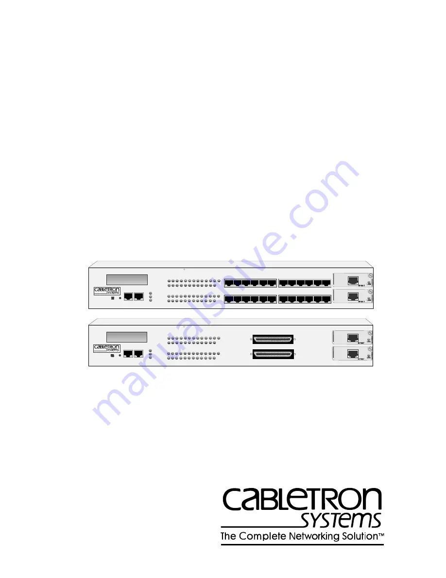
MicroMMAC-24E
10BASE-T HUB
WITH
LANVIEW
COM 1
COM 2
EPIM 1
CABLETRON
MicroMMAC-24
24
23
22
21
20
19
18
17
16
15
14
13
12
11
10
9
8
7
6
5
4
3
2
1
19X
2 0 X
2 1 X
2 2 X
2 3X
2 4 X
18X
17X
16 X
15 X
14 X
13 X
CLN
PWR
CPU
RCV
LNK
RCV
LNK
E
1
E
2
R
DISPLAY
RESET
EPIM 2
MicroMMAC-34E
10BASE-T HUB
WITH
LANVIEW
COM 1
COM 2
EPIM 1
CABLETRON
MicroMMAC-34
24
23
22
21
20
19
18
17
16
15
14
13
12
11
10
9
8
7
6
5
4
3
2
1
CLN
PWR
CPU
RCV
LNK
RCV
LNK
E
1
E
2
12X
1X
24X
13X
MicroMMAC
10BASE-T INTELLIGENT STACKABLE HUB
INSTALLATION GUIDE


