CAB HERMES Q Series, Assembly Instructions Manual
The CAB HERMES Q Series Service Manual is a must-have resource for owners and technicians, providing comprehensive instructions for maintenance, repairs, and troubleshooting. Download this invaluable manual for free from manualshive.com, ensuring you have the necessary guidance to keep your CAB HERMES Q Series performing at its best.
Share
Download


Reviews:
No comments
Related manuals for HERMES Q Series

DMW001
Brand: Dash Pages: 17

DSIM100
Brand: Dash Pages: 28

L5203
Brand: West Bend Pages: 33

Home Bakery Supreme BB-CEC20
Brand: Zojirushi Pages: 16

SCC-4000D
Brand: SwiftColor Pages: 16

BES810
Brand: Sage Pages: 14

Easy Timer 6093
Brand: Bialetti Pages: 40

Jolie & Milk
Brand: LAVAZZA Pages: 172

C-800
Brand: Gastro-M Pages: 64

JB 31
Brand: Petra Pages: 12

RYM-M5401-E
Brand: Redmond Pages: 64

CATER
Brand: Coffee Queen Pages: 24

50 Series
Brand: Ergo Pages: 10

CMF01
Brand: MOA Pages: 33

ZCM1000X
Brand: Zelmer Pages: 76
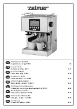
Torrido 13Z018
Brand: Zelmer Pages: 76

VINTAGE TEA PARTY
Brand: Gourmet Gadgetry Pages: 7

POD Multi-Pod 68 MB
Brand: Instant Pages: 24


