background image

8140708R10-6/09


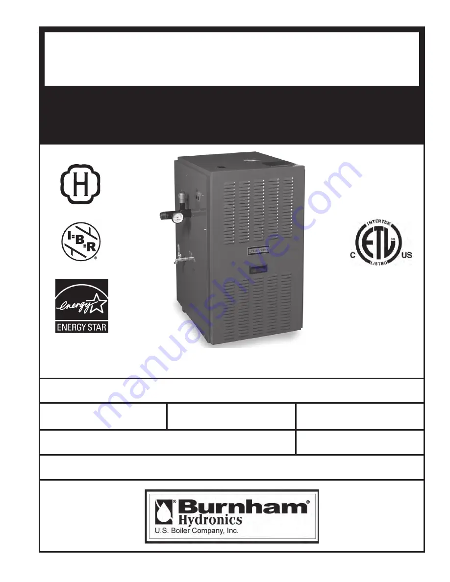
 As an ENERGY STAR

®

 Partner, Burnham Hydronics has determined that the PVG Series meets the ENERGY

  STAR

®

 guidelines for energy efficiency established by the United States Environmental Protection Agency (EPA).

Price - $5.00

n

o

n

o

i

t

a

m

r

o

f

n

i

g

n

i

k

e

e

s

n

e

h

W

.

r

o

t

c

a

r

t

n

o

c

g

n

i

t

a

e

h

r

u

o

y

ll

a

c

,

r

e

l

i

o

b

o

t

s

r

i

a

p

e

r

r

o

e

c

i

v

r

e

s

r

o

F

.

l

e

b

a

L

g

n

i

t

a

R

n

o

n

w

o

h

s

s

a

r

e

b

m

u

N

l

a

i

r

e

S

d

n

a

r

e

b

m

u

N

l

e

d

o

M

r

e

l

i

o

B

e

d

i

v

o

r

p

,

r

e

l

i

o

b

r

e

b

m

u

N

l

e

d

o

M

r

e

l

i

o

B

G

V

P

r

e

b

m

u

N

l

a

i

r

e

S

r

e

l

i

o

B

e

t

a

D

n

o

i

t

a

ll

a

t

s

n

I

r

o

t

c

a

r

t

n

o

C

g

n

i

t

a

e

H

r

e

b

m

u

N

e

n

o

h

P

s

s

e

r

d

d

A

D

N

A

G

N

I

T

A

R

E

P

O

,

N

O

I

T

A

L

L

A

T

S

N

I

R

O

F

S

N

O

I

T

C

U

R

T

S

N

I

E

C

I

V

R

E

S

G

V

P

R

E

L

I

O

B

D

E

R

I

F

-

S

A

G

Summary of Contents for PVG

Page 1: ... e h r u o y l l a c r e l i o b o t s r i a p e r r o e c i v r e s r o F l e b a L g n i t a R n o n w o h s s a r e b m u N l a i r e S d n a r e b m u N l e d o M r e l i o B e d i v o r p r e l i o b r e b m u N l e d o M r e l i o B G V P r e b m u N l a i r e S r e l i o B e t a D n o i t a l l a t s n I r o t c a r t n o C g n i t a e H r e b m u N e n o h P s s e r d d A D N A G N I T A R...

Page 2: ... the Massachusetts Board of Plumbers and Gas Fitters website http license reg state ma us pubLic pb_pre_form asp for the latest Approval Code or ask your local Sales Representative The Commonwealth of Massachusetts requires this product to be installed by a Licensed Plumber or Gas Fitter DANGER Indicates an imminently hazardous situation which if not avoided will result in death serious injury or ...

Page 3: ...l be permanently mounted to the exterior of the building at a minimum height of eight 8 feet above grade directly in line with the exhaust vent terminal for the horizontally vented gas fueled heating appliance or equipment The sign shall read in print size no less than one half 1 2 inch in size GAS VENT DIRECTLY BELOW KEEP CLEAR OF ALL OBSTRUCTIONS 4 A final inspection by the state or local gas in...

Page 4: ...e boiler is inoperative This boiler contains very hot water under high pressure Do not unscrew any pipe fittings nor attempt to disconnect any components of this boiler without positively assuring the water is cool and has no pressure Always wear protective clothing and equipment when installing starting up or servicing this boiler to prevent scald injuries Do not rely on the pressure and temperat...

Page 5: ...nimum Clearances to Combustibles I Pre Installation 7 II Unpack Boiler 8 III Venting 9 IV Water Piping and Trim 21 V Gas Piping 26 VI Electrical 29 VII Modular Installation 38 VIII System Start up 40 IX Service 47 X Repair Parts 54 ...

Page 6: ... Figure 2 Dimensions ...

Page 7: ...ement condensate trap control replacement etc I Pre Installation F Provide combustion and ventilation air in accordance with applicable provisions of local building codes or USA National Fuel Gas Code NFPA 54 ANSI Z223 1 Air for Combustion and Ventilation Canada Natural Gas or Propane Installation Code CAN CSA B149 1 WARNING Adequate combustion and ventilation air must be provided to assure proper...

Page 8: ...ied service agency E Tilt the boiler to its front side or back side and slide a wooden slat under the three raised feet F Tilt the boiler in the opposite direction and slide another wooden slat under the three raised feet G Slide the boiler left or right off the skid using the two wooden slats as runners H Move boiler to its permanent location by duct with the outdoors or spaces crawl or attic fre...

Page 9: ...t operate appliance where gasoline or other flammable vapors or liquids or sources of hydro carbons i e bleaches cleaners chemicals sprays paint removers fabric softeners etc are used stored and or present in the air When installing vent pipe through chimney no other appliance can be vented into the chimney Do not exceed maximum vent lengths Refer to Table 4 Option Description Additional Vent Kit ...

Page 10: ...1 06 TO 1 64 4 Dia Pipe x Adjustable 100179 01 3 Dia 90 Elbow 8116294U 5 4 Dia 90 Elbow 100180 01 3 Dia 45 Elbow 8116292U 5 4 Dia 45 Elbow 100181 01 3 Dia Horizontal Drain Tee 8116302U 2 4 Dia Horizontal Drain Tee 100182 01 3 Dia Vertical Drain Tee 8116304U 7 4 Dia Vertical Drain Tee 100183 01 3 Single Wall Thimble 8116116 4 Single Wall Thimble 100184 01 3 Double Wall Thimble 8116115 4 Double Wall...

Page 11: ...FPA 54 ANSI Z223 1 B General Guidelines 1 Vent system installation must be in accordance with National Fuel Gas Code NFPA 54 ANSI Z221 3 or applicable provisions of local building codes Contact local building or fire officials about restrictions and installation inspection in your area 2 Refer to the appropriate drawings in this section of this manual to determine the proper configuration of venti...

Page 12: ...tch vent systems 12 If a non standard length pipe is required Gasketed Vent System The use of the adjustable length pipe P N 8116319U is recommended to complete a non standard pipe length This pipe requires a minimum installed length of 12 inch and can adjust across a 7 inch gap up to a maximum of 19 inch long Note for the adjustable pipe the installed length should be measured from the centerline...

Page 13: ...al installation consists of vent being sloped down inch per foot away from boiler See Figure 4A See Figure 4B for an alternate horizontal installation 4 Use appropriate designed thimbles when passing through combustible walls thimble use optional for noncombustible walls Insert thimble through wall from outside Secure outside flange to wall with nails or screws and seal ID OD and vent holes with s...

Page 14: ...14 Figure 4A Recommended Horizontal Vent Installation ...

Page 15: ...15 Figure 4B Alternate Horizontal Vent Installation ...

Page 16: ...16 Figure 5 Horizontal Vent Terminal Configuration 3 or 4 Vent ...

Page 17: ... opening between the vent pipe and the structure E Separate Vertical Venting System See Figures 6 7 8 and 9 NOTICE Roof penetrations require the use of roof flashing and storm collar not supplied with boiler 5 Whenever possible install vent straight through the roof Refer to Figure 7 if offset is necessary Maintain minimum clearance to combustible materials 6 Install Vent Terminal a Size roof open...

Page 18: ...18 Figure 7 Attic Offset Figure 6 Vertical Vent Installation ...

Page 19: ...ertical Vent Termination Extend Vent Piping to maintain minimum vertical X and minimum horizontal Y distance of twelve 12 inches from roof sur face Allow additional vertical X distance for expected snow accumulation ...

Page 20: ...tails for vent pipe installation F Optional Exterior Separate Horizontal Vent Terminal Mounting See Figure 9 b After penetrating wall thimble install an AL 29 4C 90 elbow so that elbow leg is in the up direction c Install maximum of seven 7 feet of AL 29 4C vent pipe Refer to Sections C through E for proper procedures for joining vent pipe and fittings d Install AL 29 4C 45 elbow to upper AL 29 4C...

Page 21: ...with a hot water boiler IV Water Piping and Trim Where The universal location for a LWCO on both gas and oil hot water boilers is above the boiler in either the supply or return piping The minimum safe water level of a water boiler is at the uppermost top of the boiler that is it must be full of water to operate safely What Kind The PVG boiler is designed to accept the wiring of the Safgard Model ...

Page 22: ...pressure temperature gauge and pressure relief valve See Figure 10A Pressure Relief Valve must be installed with spindle in vertical position Installation of the relief valve must comply with the ASME Boiler and Pressure Vessel Code Section IV Figure 10 Recommended Piping for Combination Heating Cooling Refrigeration System WARNING Pressure relief valve discharge piping must be piped such that the...

Page 23: ...pply water temperature Opening the boiler supply valve will raise system temperature while opening the by pass valve will lower system supply temperature J After the boiler and system have been cleaned and flushed and before refilling the entire system add appropriate water treatment chemicals if necessary to bring the pH between 7 and 11 K If it is required to perform a long term pressure test of...

Page 24: ...24 Figure 11 Recommended Boiler Piping For Circulator Zoned Heating Systems ...

Page 25: ...25 Figure 12 Recommended Water Piping for Zone Valve Zoned Heating Systems ...

Page 26: ...ipment 3 Length of piping and number of fittings Refer to Table 7 for maximum capacity of Schedule 40 pipe Table 8 lists equivalent pipe length for standard fittings 4 Corrections for the specific gravity of natural gas can be found in Table 6 NOTICE PVG boilers built for altitudes greater than 4 999 feet above sea level need to be specially orificed to adjust for changes in atmospheric conditions...

Page 27: ...r the actual heating value of your gas 2 Use thread joint compounds pipe dope resistant to action of liquefied petroleum gas 3 Install sediment trap ground joint union and manual shut off valve upstream of boiler gas control valve and outside jacket See Figure 13 Length Feet 0 3 inch w c Pressure Drop 0 5 inch w c Pressure Drop 1 1 1 1 10 132 278 520 1 050 175 360 680 1 400 20 92 190 350 730 120 2...

Page 28: ...ed before placing boiler in operation 1 Protect boiler gas control valve For all testing over psig boiler and its individual shutoff valve must be disconnected from gas supply piping For testing at psig or less isolate boiler from gas supply piping by closing boiler s individual manual shutoff valve 2 Locate leaks using approved combustible gas detector soap and water or similar nonflammable solut...

Page 29: ...ck once power is turned off WARNING Failure to properly wire electrical connections to the boiler may result in serious physical harm Electrical power may be from more than one source Make sure all power is off before attempting any electrical work Each boiler must be protected with a properly sized over current device Never jump out or make inoperative any safety or operating controls The wiring ...

Page 30: ...30 Figure 14 Internal Boiler Wiring Schematic Diagram ...

Page 31: ...31 Figure 15 Internal Boiler Wiring Ladder Diagram NOTICE If an additional system limit is used install in series with the auxiliary limit jumper shown in the drawing below ...

Page 32: ... 1 zone the first zone of the main control will provide priority circulation If more than four 4 zones are required connect additional R8888 s by wiring the A B and C terminals of each control together Each R8888 requires a 120 volt power supply If more than one 1 R8888 is used set the panel type switch to main on the first R8888 and set the panel type switch to expansion on the second third or fo...

Page 33: ...33 Figure 16 Single Heating Zone Only Wiring Schematic ...

Page 34: ...igure 17 Single Zone System with Packaged Alliance SL Water Heater Wiring Schematic NOTICE If an additional system limit is used install in series with the auxiliary limit jumper shown in the drawing below ...

Page 35: ...35 Figure 18 Circulator Zoned System Wiring Schematic ...

Page 36: ...36 Figure 19 Zone Valve Zoned System Wiring Schematic ...

Page 37: ...37 Figure 20 Different Manufacturer s Zone Valve Connections to Honeywell R8889 ...

Page 38: ... be made Each vent termination must be one 1 foot from other terminations D Water Piping See Table 9 and Figure 21 Installing a low water cutoff in the system piping of modular systems is strongly recommended and may be required by Local Codes E Gas Piping 1 Refer to National Fuel Gas Code Local Codes and Tables 7 and 8 for gas pipe sizing VII Modular Installation Table 9 Modular Boiler Water Mani...

Page 39: ...39 Figure 21 Modular Boiler Piping ...

Page 40: ...ly piping Note Terminate hose in five gallon bucket at a suitable floor drain or outdoor area VIII System Start up 4 Starting with one circuit at a time open zone valve or shut off valve in system supply and return piping 5 Open hose bib 6 Open fill valve Make up water line should be located directly after full port ball valve in system supply piping between air scoop and expansion tank 7 Allow wa...

Page 41: ...41 Figure 22 Operating Instructions ...

Page 42: ...cations Perform routine maintenance to assure optimum flame signal 1 Marginal Flame Signal less than 1 1 µA System may not operate reliably over time Service call recommended Note This indication may flash temporarily during or shortly after lightoff on some applications Check gas supply pilot burner flame sense wiring contamination of flame rod burner ground connection OFF No Flame or Flame Signa...

Page 43: ...secondary voltage supply below 15 5 Vac Control remains in wait mode When the fault corrects control resumes nor mal operation after one minute delay Check transformer and AC line for proper input voltage to the control Check with full system load on the transformer 6 2 5 minute Retry Delay On every third retry on same Call for Heat Initiate new trial for ignition after retry delay completed Check...

Page 44: ...44 Honeywell Electronic Ignition Troubleshooting Guide Figure 24 Troubleshooting Guide ...

Page 45: ...erature setting to start and stop boiler operation M Check ignition control module shut off Disconnect pilot lead wires from gas valve If burners do not shutdown determine cause of malfunction Replace necessary items and check operation N Check low water cutoff if so equipped 1 Adjust thermostat to highest setting 2 With boiler operating open drain valve and slowly drain boiler 3 Main burners and ...

Page 46: ...lt 4 Determine Input Rate Multiply gas flow rate by gas heating value 5 Compare measured input rate to input rate stated on rating plate a Boiler must not be over fired Reduce input rate by decreasing manifold pressure Do not reduce more than 0 3 inch w c If boiler is still overfired contact your U S Boiler distributor or Regional Office for replacement Gas Orifice b Increase input rate if less th...

Page 47: ... tube to drain fitting providing gas tight and watertight seal 7 If pipe must be disassembled for removal of obstructions or resealing of joint see Section III Paragraph C D Boiler Flue Passages Inspect for blockage or soot accumulation 1 Remove Main Burners See Figure 30 a Remove front door b Disconnect pilot tubing and pilot lead wires at the gas valve c Remove wires to Flame Roll out Switch d R...

Page 48: ... through bushings in Vestibule Panel See Figure 28 13 Install Jacket Top Rear Panel 14 Connect vent system See Figure 29 15 Connect Blower Motor Wiring Harness E Main Burners and Firebox 1 Vacuum firebox Exercise care do not damage base insulation 2 Clean main burners Brush top of burners with soft bristle brush See Figure 30 Vacuum to remove any dirt and lint 3 Vacuum tip of pilot burner 4 Check ...

Page 49: ...49 Figure 30 Flue and Burner Cleanout 1 Burner ...

Page 50: ...nect hoses to differential pressure switch See Figures 28 and 31 Figure 31 Differential Pressure Measurement Table 15 Differential Pressure Switch Settings Boiler Model Main Burner with Pilot Bracket Pilot Burner Located Between Main Burners PVG 3 2 2 3 PVG 4 3 3 4 PVG 5 4 4 5 PVG 6 5 5 6 PVG 7 6 6 7 PVG 8 7 7 8 PVG 9 8 8 9 Main burners numbered left to right as viewed from front of boiler Boiler ...

Page 51: ...51 THIS PAGE LEFT BLANK INTENTIONALLY ...

Page 52: ...52 ...

Page 53: ...53 ...

Page 54: ... U S Boiler Wholesale distributor Should you require assistance in locating a U S Boiler distributor in your area or have questions regarding the availability of U S Boiler products or repair parts please contact U S Boiler Customer Service at 717 481 8400 or Fax 717 481 8408 ...

Page 55: ...n 1 71707003 2 71707003 3 71707003 4 71707003 5 71707003 6 71707003 7 71707003 1C Right End Section 71707002 1D Slip Nipple 3 4 806600009 6 806600009 8 806600009 10 806600009 12 806600009 14 806600009 16 806600009 1E Flue Gas Baffle 2 71107002 3 71107002 4 71107002 5 71107002 6 71107002 7 71107002 8 71107002 1F Tie Rod 20 2 100109 01 2 100108 05 2 100108 07 2 100108 13 2 100108 14 2 100108 15 2 10...

Page 56: ...56 ...

Page 57: ...ner Access Panel 71807036 71807046 71807056 71807066 71807076 71807086 71807096 2F Cerafelt Gasket 1 2 x 2 6206002 2G Cerafelt Gasket 1 2 x 2 6206002 2H Base Side Insulation 2 72007001 2J Base Rear Insulation 72007031 72007041 72007051 72007061 72007071 72007081 72007091 2K Base Front Insulation 72007032 72007042 72007052 72007062 72007072 72007082 72007092 2L Base Leg Assembly 4 6186001 2M Self T...

Page 58: ...VG 6 PVG 7 PVG 8 PVG 9 3 BASE ASSEMBLY 3A Burner Cover Natural Gas Only 102033 03 102033 04 102033 05 102033 06 102033 07 102033 08 102033 09 3B Manifold Support Bracket 718070001 3C Sheet Metal Screw 8 x 1 2 2 80860000 3D Self Tapping Screw 10 32 x 3 8 6 80860705 ...

Page 59: ...7031 61107041 61107051 61107061 61107071 61107081 61107091 Canopy Assembly High Altitude 61107032 61107042 61107052 61107062 61107072 61107082 61107092 4B Cerafelt 9206005 4C U Clip 4 80861512 4D Sheet Metal Screw 10 x 1 4 808600141 4E Fan Gasket 8206085 4F Fan 81161512 4G Lock Washer 10 4 80860636 4H Machine Screw 10 24 x 2 1 2 4 808608982 ...

Page 60: ...60 ...

Page 61: ... Union NPT 806604023 N A Union NPT N A 806604001 5D Gas Manifold 82207031 82207041 82207051 82207061 Gas Manifold 82207071 82207081 82207091 5E Burner Orifices Natural Gas 47 4 822710 6 822710 8 822710 10 822710 12 822710 14 822710 16 822710 Burner Orifices LP Gas 1 20 mm 4 822792 6 822792 8 822792 10 822792 12 822792 14 822792 16 822792 5F Pilot Assembly Natural Gas 8236163 Pilot Assembly LP Gas ...

Page 62: ...189 01 6B Transformer Relay Honeywell R8285D 80160155U 6C Ignition Module Honeywell S8670E3003 100959 01 6D Blower Relay Honeywell R8222U1006 80160096U 6E Differential Pressure Switch Sea Level 0 4999 80160762 80160761 80160760 80160759 80160760 High Altitude 5000 10 000 80160759 80160763 80160764 80160765 80160764 6F Junction box 8136259 ...

Page 63: ...407063 60407073 60407083 60407093 7D Vestibule Panel 60407034 60407044 60407054 60407064 60407074 60407084 60407094 7E Top Panel 60407032 60407042 60407052 60407062 60407072 60407082 60407092 7F Front Door 101354 03 101354 04 101354 05 101354 06 101354 07 101354 08 101354 09 7G Jacket Cover Plate 80407001 7H Handle 8056184 7J Door Clip 2 7041921 7K Bushing 8136048 7L Burnham Hydronics Logo 8146009...

Page 64: ...PVG 8 PVG 9 8 MISCELLANEOUS PARTS CARTON 8A Water Manifold 80607001 8B Temperature Pressure Gauge 100282 01 8C Circulator Wiring Harness 6130701 8D Safety Relief Valve 81660363 8E Boiler Drain Valve 806603061 8F Vent Terminal 8110701 8110702 8G Vent Connector 8110703 8110704 ...

Page 65: ... Long sleeved loose fitting clothing 3 Gloves 4 Eye Protection Take steps to assure adequate ventilation Wash all exposed body areas gently with soap and water after contact Wash work clothes separately from other laundry and rinse washing machine after use to avoid contaminating other clothes Discard used RCF components by sealing in an airtight plastic bag RCF and crystalline silica are not clas...

Page 66: ...66 SERVICE RECORD DATE SERVICE PERFORMED ...

Page 67: ...67 SERVICE RECORD DATE SERVICE PERFORMED ...

Page 68: ...einstalling the alleged defective part or its replacement and all labor and material connected therewith and transportation to and from U S Boiler Company Inc b Components that are part of the heating system but were not furnished by U S Boiler Company Inc as part of the residential boiler c Improper burner adjustment control settings care or maintenance d This warranty cannot be considered as a g...

Reviews: