Buhnen HB 710 Spray, Operating Manual
The Buhnen HB 710 Spray is a powerful and versatile tool for all your spraying needs. Ensure optimal performance by following the detailed instructions in the Operating Manual. Download it for free from manualshive.com to unlock the full potential of this high-quality product.
Share
Download


Reviews:
No comments
Related manuals for HB 710 Spray
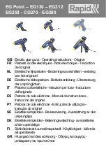
EG Point
Brand: Rapid Pages: 35

RTM404
Brand: RTRMAX Pages: 9

BNS200-18
Brand: Bosch Pages: 42

FNA-250-15
Brand: Bosch Pages: 42

FNH180-16B
Brand: Bosch Pages: 76

GSK 64
Brand: Bosch Pages: 332

GSK 50
Brand: Bosch Pages: 351

M643
Brand: Performance Tool Pages: 4

R138HPF
Brand: RIDGID Pages: 36

Coil Nailer SCN45
Brand: Senco Pages: 2

10P0001N
Brand: Senco Pages: 9

5J0001N
Brand: Senco Pages: 12

41
Brand: Senco Pages: 16

N400
Brand: Bostitch Pages: 58

DPT350RFJ
Brand: Makita Pages: 48

557DC
Brand: BEA Pages: 51

Nailer SLP20XP
Brand: Senco Pages: 4

GSN65
Brand: Toua Pages: 2


