


Installation and Service
Instructions
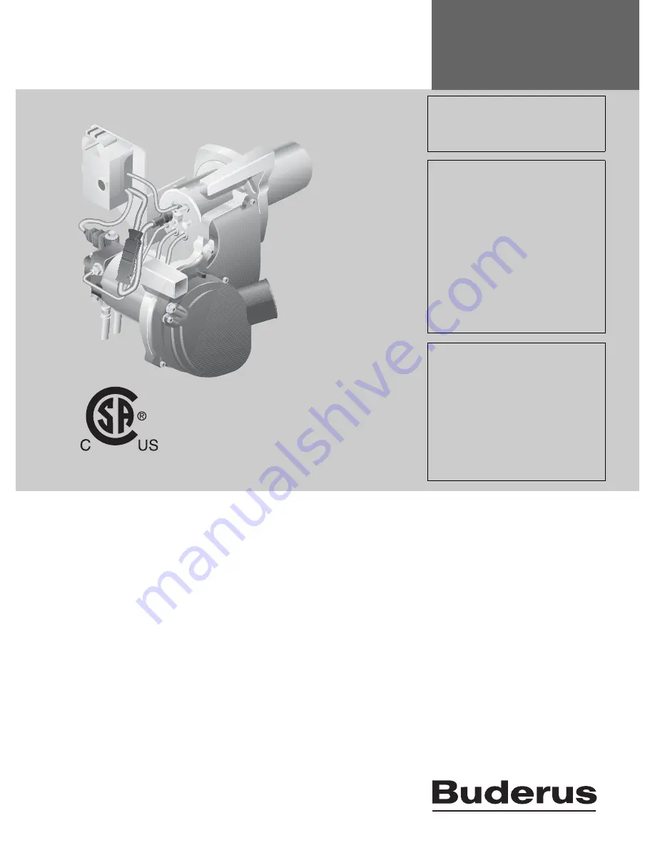
Low Emissions Blue
Flame Oil Burner
Logatop BE 1.3 and 2.3
6 720 80
4 882 (20
12/10) EN-US
For trained installers
Read carefully prior to
installation, maintenance
and service.
CAUTION!
Read this manual carefully before putting
this burner into operation.
WARNING!
This burner requires special training and
a specific tool kit. Do not attempt installa-
tion and/or service unless you are a Bud-
erus trained and certified technician
equipped with the proper tools and mea-
surement equipment.
Improper installation, adjustment, alter-
ation, service or maintenance can cause
property damage, personal injury, or loss
of life. Refer to this manual.
For assistance or additional information
consult a Buderus trained installer, ser-
vice agency or oil company.
CAUTION!
The operating manual is part of the docu-
mentation that is delivered to the installa-
tion's operator. Go through the
information in this manual with the own-
er/operator and make sure that he or she
is familiar with all the necessary operating
instructions.
Notice! This manual must be retained for future reference.


