Brother S-7200A, Instruction Manual
The Brother S-7200A is a versatile sewing machine designed for both professional and personal use. Its user-friendly features make it perfect for beginners, and with the Basic Operation Manual available for free download from manualshive.com, you can effortlessly master this machine and unleash your creativity.
Share
Download


Reviews:
No comments
Related manuals for S-7200A

1200D
Brand: Janome Pages: 2

KX-FP121
Brand: Panasonic Pages: 136

UF 890 - Panafax B/W Laser
Brand: Panasonic Pages: 174

659
Brand: Janome Pages: 25

8309-023
Brand: Pfaff Pages: 54

MC-35M
Brand: Magnum Pages: 11

KMR 1700 D
Brand: Kärcher Pages: 26

VF Stratus
Brand: Viruserv Pages: 6

MINI-VACTOR
Brand: HAWK ENTERPRISES Pages: 16

FUTURA QUARTET SEQS-6000
Brand: Singer Pages: 112

Fax 680 MP
Brand: Ricoh Pages: 84

HZL-60ce
Brand: JUKI Pages: 20

HZL-60 CE
Brand: JUKI Pages: 28

HZL-E70
Brand: JUKI Pages: 52

Exceed F-300
Brand: JUKI Pages: 164

DLN-415
Brand: JUKI Pages: 15

NC81200 CLASSES
Brand: Carpet Sergers Pages: 30
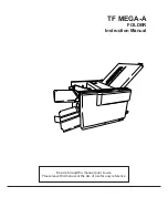
TF MEGA-A
Brand: Hefter Pages: 71


