


Installation and Operation Manual
X -TMF-5965-5851EM-MFC-eng
Part Number: 541B122AAG
September, 2009
Brooks
®
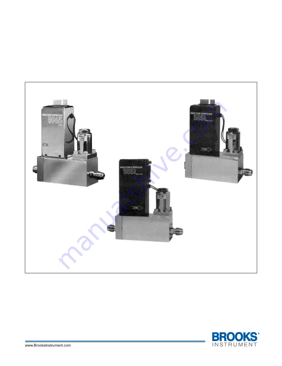
Models 5965, 5851EM
Brooks
®
Models 5965, 5851EM
Mass Flow Controllers
Model 5851EM
Mass Flow Controller
with D-Connector
Model 5851EM Downported
Mass Flow Controller
with Card Edge
Model 5965
Mass Flow Controller
with Card Edge


