Broil King H3X-1, Owner'S Manual
The Broil King H3X-1 Owner's Manual is available for free download on our website. This comprehensive manual provides detailed instructions and insightful tips on operating and maintaining your Broil King H3X-1 grill. Easily access and download this invaluable manual at manualshive.com, enhancing your grilling experience.
Share
Download


Reviews:
No comments
Related manuals for H3X-1

HP332D
Brand: Makita Pages: 20

SC5812
Brand: Sunco living Pages: 30

98110
Brand: Bullet Barbecue Pages: 20

126067930
Brand: Outdoor Gourmet Pages: 17

VANGUARD G53902
Brand: Vermont Castings Pages: 56

VR 230 614
Brand: Gaggenau Pages: 32

UH 240-A
Brand: Hilti Pages: 34

Feed Life ZPG-700E Series
Brand: Z GRILLS Pages: 21

BS 18 V
Brand: Mafell Pages: 48

MAGIC GR2600
Brand: Jata Pages: 24

55570
Brand: Weber Pages: 31

8069676
Brand: Power Fist Pages: 14

Professional VEOS100T
Brand: Viking Pages: 6

53135
Brand: Dynabrade Pages: 8

P-AS 3,6 Li
Brand: Parkside Pages: 64

ASCD 18-200 W4
Brand: Fein Pages: 187

315.277180
Brand: Craftsman Pages: 18
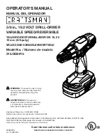
315.DD2015
Brand: Craftsman Pages: 20


