background image

Brobo Group 


brobo.com.au 


©


BROBO GROUP (AUST) PTY. LTD. 

8 Fowler Rd, Dandenong South 
Victoria 3175, AUSTRALIA.


  + 61 3 9794 8751


📧


[email protected]


🖷

 + 

61 3 9794 8792 


www.brobo.com.au


PRODUCT & MAINTENANCE MANUAL 


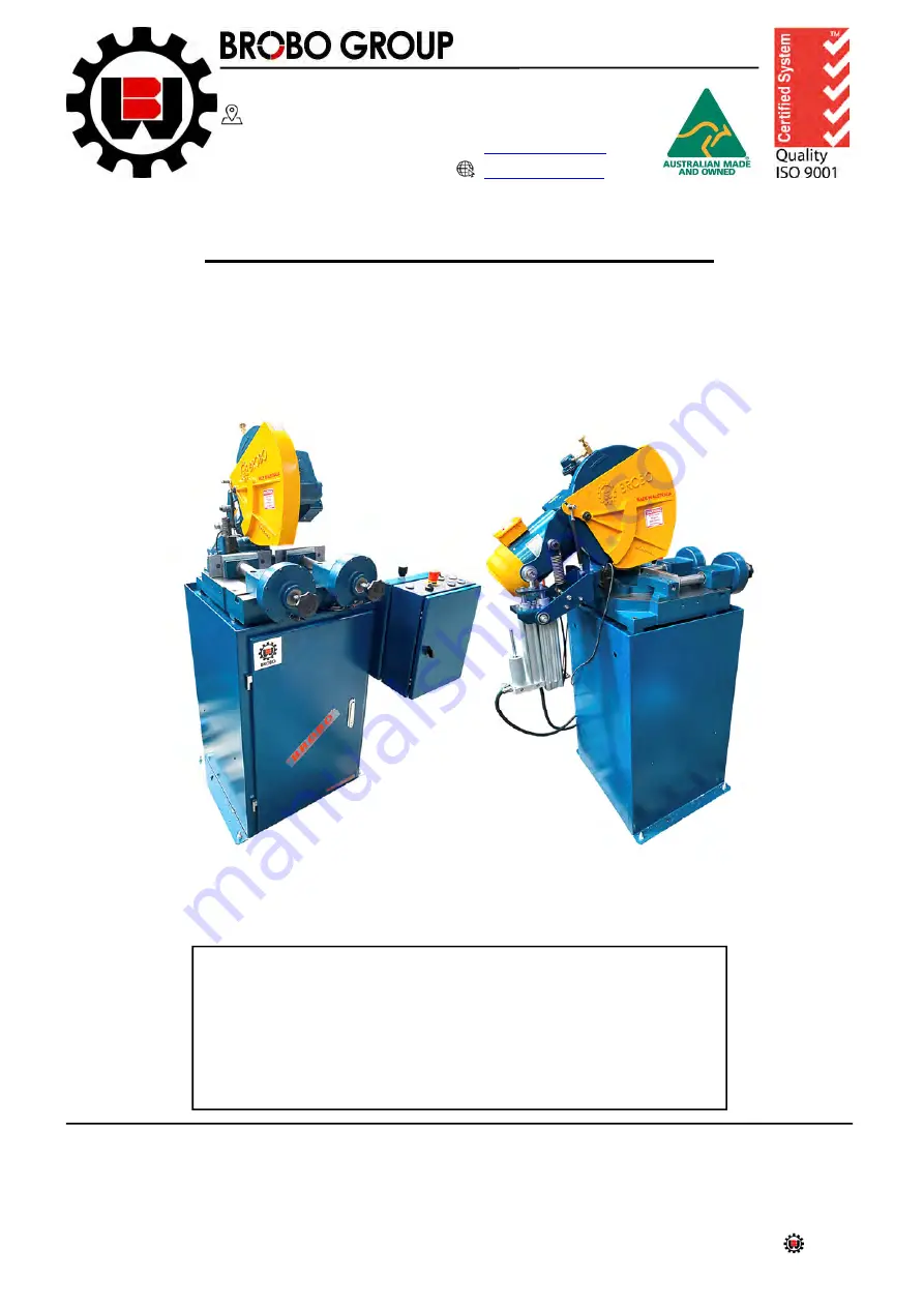
SEMI-AUTOMATIC HYDROCHECK SAW


MODEL No. SA350H, SA400H 


   Precision Drilling Machines   

   Tapping Machines   

   Multi-Head Drills   

   Tool Grinders   


   Tool Post Grinders   

   Machine Vices   

   Special Production Equipment   


   Accessories   

   Riveting Machines   

   Pedestal Grinders   

   Metal Cutting Saws   

   Linishers   


YOUR BROBO DISTRIBUTOR IS:


A.C.N.      

098 264 316 

A.B.N. 

42 098 264 316


Summary of Contents for SA350

Page 1: ... au PRODUCT MAINTENANCE MANUAL SEMI AUTOMATIC HYDROCHECK SAW MODEL No SA350H SA400H Precision Drilling Machines Tapping Machines Multi Head Drills Tool Grinders Tool Post Grinders Machine Vices Special Production Equipment Accessories Riveting Machines Pedestal Grinders Metal Cutting Saws Linishers YOUR BROBO DISTRIBUTOR IS A C N 098 264 316 A B N 42 098 264 316 ...

Page 2: ...x 3 2 Preparation for Operation 3 3 Operation Recommendations CHAPTER 4 Drawings Layouts Assembly Spare Parts 4 1 1 Cold Saw Main Dimensions 4 1 2 Cold Saw Assembly 4 2 1 Standard Gearbox Assembly 4 2 2 Gearbox Assembly 400 4 2 3 Coolant Tank Assembly 4 2 4 Motor Assembly 4 3 1 Pneumatic Vice Assembly 4 3 2 Pneumatic Electrical Diagram 4 3 3 Broborule Series CHAPTER 5 Adjustments to the Saw Unit 5...

Page 3: ... 200 200 220 4 160 180 180 5 140 160 180 100 1 300 300 340 2 220 200 220 3 200 180 180 4 160 140 160 5 140 120 140 120 1 300 340 2 200 220 3 180 180 4 160 160 5 120 140 SOLID SECTIONS 10 280 280 300 20 160 200 240 30 140 160 200 40 120 140 140 50 80 100 120 60 80 100 TABLE 2 Blade Selection Chart Blade Type High Speed Steel HSS 180 Tooth Blade 350mm x 40mm bore NOTE CHART GUIDE ONLY This chart is ...

Page 4: ...pm Worm Gear Drive Ratio 1 33 Reduction No of Starts Shaft No Teeth Wormwheel Sound Level dBA 85 90 dB A Maximum Spindle Speed Dual Speed Selection 21 42 RPM VICE CLAMPS Pneumatic Vice Clamping Range mm 0 135 145mm w o wear plates Air Requirements Dry filtered lubricated air supply Air Consumption L 1 6 Litre per cycle per vice cylinder Clamp Working Pressure kPa 600kPa 6 Bar 87psi Maximum Pressur...

Page 5: ...ed on a full size blade The capacities will reduce accordingly when a worn blade is resharpened DIMENSIONAL SPECIFICATIONS Base Dimensions L W 550mm 660mm Table Working Height 968 mm Saw Height 1480 mm SAW WEIGHT Packaged SA350 278 kg SA400 280 kg TABLE 4 Cutting Range ...

Page 6: ...rea as close as possible to the final location Carefully remove the wooden frame surrounding the saw unit Figure 1 Once completed proceed by elevating the machine away from the pallet base using a sling harness wrapped around the cutting head of the saw Ensure that the floor is as level as possible before finally positioning the machine to the desired location FIGURE 1 Handling of Semi Automatic C...

Page 7: ...m 150mm pitch 9501740 Fabricated Sheet Metal Stand 9301450 Floor Stand Angle Iron 9501640 Brobolube Additional Blade s Custom to Client Requirements 1 3 Minimum Requirements For the machine to function correctly the room in which the saw unit is to be installed must be in the vicinity of satisfy the following conditions 240 415V Power Supply Working Pressure Not less than 600kPa 6 Bar no greater t...

Page 8: ...ibility to cut parts safe access for the operator The base of the fabricated stand if applicable in which the saw head rests on is anchored to the floor by 4 M12 bolts provided For added stability it is strongly recommended that the machine stand is fastened to the floor by using loxins not provided When positioning fastening the unit please refer to the hole locations shown in Figure 2 Figure 2 A...

Page 9: ...pproved 5 pin plugs Australia Figure 3 2 Connection for 5 CORE Wire System with Neutral 3 Phase c Check the power supplied motor specifications before plugging in the machine Check the terminal connection on dual voltage motor terminal box connect it accordingly to the corresponding voltage supply d If the dual motor is requested the motor is always connected to the higher voltage unless otherwise...

Page 10: ...irection acting to release the piece when the saw is not running clamp what saw is running 5 Check that the motor is operating in the correct direction that is the blade is rotating downwards into the direction of the vice clamps 6 Ensure that all electrical leads cables including supply leads are maintained in good condition away from sharp objects All leads should be replaced if cut sliced or da...

Page 11: ...ON MACHINERY No 98 37 CE Danger Zone any zone in and or around a machine in which the presence of a person constitutes a risk to the safety health of that person Person Exposed any person finding him or herself either completely or partly in a danger zone Operator the person or persons are given the responsibility of installing operating adjusting maintaining cleaning repairing transporting the ma...

Page 12: ...Requirements Lighting Insufficient lighting during the operation of the saw unit would constitute a safety hazard for the people concerned For this reason the user of the machine must provide adequate lighting in the working area to eliminate areas of shadow whilst also preventing dazzling illumination sources Reference standard ISO 8995 2002 Lighting of Indoor Workplaces Connection Check that the...

Page 13: ... tied back or placed in a hair net Always disconnect the power supply to the machine before carrying out any maintenance work or adjustments This includes cases of abnormal operations of the machine Any maintenance work performed on the hydraulic pneumatic or coolant systems must be carried out only after the pressure in the system has been released The operator MUST NOT conduct any risky operatio...

Page 14: ... Always follow safe practices inspection procedures when installing blades Please refer to section 5 1 Changing the Blade When cutting very small specimens ensure that the workpiece is not dragged behind the back fence support where it could get lodged behind the blade If the blade jams during a cut activate the emergency stop function immediately Do not continue forcing the blade through This cou...

Page 15: ...on the saw also complies with the Australian Standards regarding the safeguarding general requirements for electrical equipment 2 4 1 Reference Standards MACHINE SAFETY EEC Directive No 98 37 CE Machines Directive EEC Directive No 91 368 94 68 Amends sections of EEC Directive No 98 37 CE relating to machine safety EEC Directive No 73 23 Low Voltage Directive AS4024 1 1996 Safeguarding of Machinery...

Page 16: ...f the final cuts In addition the use of correct saw blade provides minimum burr to the workpiece while maximizing the safety to the operator during each cutting procedure 3 1 2 Saw Safety Guard The primary purpose of the saw safety guard Figure 9 is to protect the user from the spinning blade It also functions as a safety device to protect the operator from any broken tooth swarf or high velocity ...

Page 17: ...de of the piston to the other via a transfer tube and needle valve which adjusts checking rate 3 1 4 Pneumatic Vice Clamp Operating at 600kPa the vice clamps Figure 11 firmly secure the workpiece in preparation for cutting The pressure of each vice clamp could be modified using the pressure regulators located on the main electrical unit door Each vice must be adjusted manually to accommodate vario...

Page 18: ...test possible time This system works reliably on all RHS round sections however for some profile sections it will fail to detect the end of the cut finish cutting too early The operator can turn this on off using the END CUT DETECT button When switched off the saw makes the deepest possible cut It is also possible to limit the cut depth while END CUT DETECT is on by unscrewing the depth adjustment...

Page 19: ...command 4 Angle Adjustment To adjust the cutting angle untighten the quick action handle as shown in Figure 10 Fine tune the angle required then re tighten the quick action handle 5 Vice Clamp Setting Place the cutting specimen you wish to cut into the vice clamps With a pneumatic vice manually adjust the clamps so that the jaws are clamped firmly to the workpiece or with a clearance of 3 7mm Figu...

Page 20: ...e it will rise slightly then stop moving At this point the vice will release the piece The saw is now ready to cut the workpiece 8 CUT Button When ready to cut press the two CUT buttons simultaneously Figure 18 The vices will clamp the workpiece the blade will being to rotate the saw will lower to cut the piece Once the cut is complete the vices will release the workpiece the saw will return to th...

Page 21: ...in the upright position for more than 3 minutes otherwise damage can occur to the drive system The rate of feed affects the quality of the final cut blade life This varies also by the material cross sectional dimensions When cutting stainless steel or high carbon steel Brinell hardness above 200 the slowest speed machine should be used together with a cobalt type high speed steel blade As a rule o...

Page 22: ...RATING ZONE UNLESS OTHERWISE SPECIFIED DIMENSIONS ARE IN MILLIMETERS SURFACE FINISH TOLERANCES LINEAR ANGULAR MATERIAL DO NOT SCALE DRAWING REVISION TITLE DWG NO SCALE 1 10 SHEET 1 OF 1 A3 WEIGHT 001002 SEMI AUTO SAW G MAIN DIMENSIONS BROBO GROUP Address 8 Fowler Rd Dandenong VIC 3175 https brobo com au 06 12 2021 0 DRAWN DATE ANH ALL RIGHTS RESERVED THIS DRAWING MAY NOT BE REPRODUCED OR TRANSMITT...

Page 23: ...8715210 Hex Lock Nut 2 16 8706150 Linkage Shoulder Bolt M6x5 1 17 8705790 Washer16x8 4x1 6 3 ITEM NO PART NUMBER DESCRIPTION QTY 1 SAHCT Hydrocheck Clamping Table Kit 1 2 SA350GBH Semi Auto Saw Gearbox Complete 1 3 OGE Outer Guard Complete 1 4 9501300 Semi Auto Saw Link Assembly 1 5 DMC50200 Hydrocheck Unit 1 6 5001060 Spring 150 1 7 9501740 Cold Saw Stand Assembly 1 8 9901280 Hydrocheck Enclosure...

Page 24: ...1 21 9712030 Pivot Block for H model 1 22 9304030 Pivot Shaft 1 23 8705140 Socket Head Cap Screw M8x35 1 24 8715210 Hex Thin Lock Nut M8 1 25 8715050 Dowel Pin 6x30 2 26 8725500 Socket Head Cap Screw M10x35 4 27 8705650 Socket Head Cap Screw M12x25 6 28 9911100 Bracket LH CMG 1 29 9911090 Bracket RH CMG 1 30 9911180 Wheelbarrow Bearing OD35 ID3 4 2 31 9911520 Cylinder Bearing Insert 2 32 9911140 B...

Page 25: ...ew M12x40 1 17 9712030 Pivot Block for H model 1 18 8705650 Socket Head Cap Screw M12x25 6 19 9911100 Bracket LH CMG 1 20 9911090 Bracket RH CMG 1 21 9911180 Wheelbarrow Bearing OD35 ID3 4 2 22 9911520 Cylinder Bearing Insert 2 23 9911140 Bracket Lower Support 1 24 8705720 Hex Nut M8 4 25 8705160 Socket Head Cap Screw M10 x 20 2 26 9901300 Spring Hook Roller Bottom 1 27 9910100 Encoder Assembly 1 ...

Page 26: ...rbox Cover Plate 1 5 8726100 Button Head Socket Screw M6x16 2 6 9911560 M20 Plug 1 7 9105050 Coolant Tap 1 8 9502040 Inner Guard 1 9 8705050 Socket Head Cap Screw M6x12 3 10 9505023 Motor 2 2Kw 4 Pole 1 11 9304660 Spacer Ring SA 45x28x16 5 1 12 9505380 Coupling Half L100 24 1 13 9505022 Ring Kit 1 14 9505021 Coupling Half L100 28 1 15 8725770 Socket Head Cap Screw 4 16 9901290 Spring Hook Roller T...

Page 27: ...ED DIMENSIONS ARE IN MILLIMETERS SURFACE FINISH TOLERANCES LINEAR ANGULAR MATERIAL DO NOT SCALE DRAWING REVISION TITLE DWG NO SCALE 1 1 SHEET 1 OF 1 A3 WEIGHT 9910100 ENCODER ASSEMBLY BROBO GROUP Address 8 Fowler Rd Dandenong VIC 3175 https brobo com au 21 01 2021 0 DRAWN DATE ANH ALL RIGHTS RESERVED THIS DRAWING MAY NOT BE REPRODUCED OR TRANSMITTED IN ANY FORM OR BY ANY MEANS IN PART OR IN WHOLE ...

Page 28: ...0 Coolant Pump 1 19 9324070 Pump Mounting Plate 1 20 9304017 Pin Coolant Pump 1 21 8705560 Hex Head Screw M8x20 2 22 9505030 Nylon Hose Kit 8mm 1 23 9314050 WormWheel 1 24 9305010 Double Seal 90x70x10 1 25 9504080 Main Spindle S315 S350 1 26 9314420 Key Main Spindle 1 27 9504090 Spindle Counter Plate S315D S350D 1 28 8715080 Dowel Pin 8x25 2 29 8735090 Retaining Screw M16x40 LEFT HAND Threaded 1 3...

Page 29: ...SH TOLERANCES LINEAR ANGULAR MATERIAL DO NOT SCALE DRAWING REVISION TITLE DWG NO SCALE 1 2 SHEET 2 OF 2 A3 WEIGHT 9935260 STANDARD GEARBOX ASSEMBLY S350 BROBO GROUP Address 8 Fowler Rd Dandenong VIC 3175 https brobo com au 25 10 2021 0 DRAWN DATE ANH ALL RIGHTS RESERVED THIS DRAWING MAY NOT BE REPRODUCED OR TRANSMITTED IN ANY FORM OR BY ANY MEANS IN PART OR IN WHOLE WITHOUT THE WRITTEN PERMISSION ...

Page 30: ... 18 9405450 Coolant Pump 1 19 9324070 Pump Mounting Plate 1 20 9304017 Pin Coolant Pump 1 21 8705560 Hex Head Screw M8x20 2 22 9505030 Nylon Hose Kit 8mm 1 23 9314050 WormWheel 1 24 9305010 Double Seal 90x70x10 1 25 9814010 Main Spindle S400 1 26 9314420 Key Main Spindle 1 27 9824000 Spindle Counter Plate S400 1 28 8715140 Dowel Pin 12x30 2 29 8735090 Retaining Screw M16x40 LEFT HAND Threaded 1 30...

Page 31: ...ION TITLE DWG NO SCALE 1 5 SHEET 1 OF 1 A3 WEIGHT 9311110 COOLANT TANK ASSEMBLY BROBO GROUP Address 8 Fowler Rd Dandenong VIC 3175 https brobo com au 05 06 2020 0 DRAWN BY DATE ANH ALL RIGHTS RESERVED THIS DRAWING MAY NOT BE REPRODUCED OR TRANSMITTED IN ANY FORM OR BY ANY MEANS IN PART OR IN WHOLE WITHOUT THE WRITTEN PERMISSION OF BROBO GROUP PTY LT SIZE TO MATCH CAST 6 mm 0 1 0 5 30 mm 0 2 0 5 10...

Page 32: ...e 1 9503130 SHEETMETAL STAND ITEM NO PART NUMBER DESCRIPTION QTY 14 9503130 C01 Front 1 15 9503130 C02 Back 1 16 9503130 C03 Top 1 17 9503130 C04 Rod 4 18 9503130 C05 Bended Equal Angle 1 6x50x515 2 19 9503150 Saw Stand Shelf 1 UNLESS OTHERWISE SPECIFIED DIMENSIONS ARE IN MILLIMETERS SURFACE FINISH TOLERANCES LINEAR ANGULAR MATERIAL DO NOT SCALE DRAWING REVISION TITLE DWG NO SCALE 1 10 SHEET 1 OF ...

Page 33: ...4 8705940 Roll Pin 4x24 1 15 8735490 Button Head Cap Screw M6x12 8 16 2l34002 4 1 8 Fox Swivel Elbow 2 17 8705290 Socket Head Cap Screw M12x75 2 18 9314280 Vice Block Clamp 2 19 8705340 Flat Socket Head Cap Screw M6x16 4 UNLESS OTHERWISE SPECIFIED DIMENSIONS ARE IN MILLIMETERS SURFACE FINISH TOLERANCES LINEAR ANGULAR MATERIAL DO NOT SCALE DRAWING REVISION TITLE DWG NO SCALE 1 5 SHEET 1 OF 1 A3 WEI...

Page 34: ...M10x25 4 ITEM NO PART NUMBER DESCRIPTION QTY 1 9505910 Carriage Track 3 0 Metre 1 2 9505940 Measuring Tape 5Mx19 1 3 9512110 Angle Bracket 3 4 8705570 Button Head Cap Screw M8x40 3 5 8705580 Hex Head Screw M8x40 3 6 9501560 Mirco Flip Included Arm 1 7 9501210 Brobo 68 Kg Conveyor Roller 3000x305x150mm Pitch 1 UNLESS OTHERWISE SPECIFIED DIMENSIONS ARE IN MILLIMETERS SURFACE FINISH TOLERANCES LINEAR...

Page 35: ...TEM NO PART NUMBER DESCRIPTION QTY 1 9505900 Carriage Track 6 0 Metre 1 2 9505950 Measuring Tape 8Mx19 1 3 9512110 Angle Bracket 6 4 8705570 Button Head Cap Screw M8x40 6 5 8705580 Hex Head Screw M8x40 6 6 9501560 Mirco Flip Included Arm 1 7 9501210 Brobo 68 Kg Conveyor Roller 3000x305x150mm Pitch 2 UNLESS OTHERWISE SPECIFIED DIMENSIONS ARE IN MILLIMETERS SURFACE FINISH TOLERANCES LINEAR ANGULAR M...

Page 36: ...16 1x17 34 5x3 2 16 9504020 Mounting Plate Shape L2 1 17 9505930 Stop Plate 99 x 85 x 6 1 18 9502100 Extension Arm Stop 1 19 9504840 Wear Plate 50x40x5 1 20 8705340 Flat Socket Head Cap Screw M6x16 5 21 8715080 Dowel Pin 8x25 1 22 8705130 Socket Head Cap Screw M8x25 1 23 8705070 Socket Head Cap Screw M6x20 3 24 9504830 45 Offset Indicator 1 25 8705930 Slotted Spring Pin 4x16 2 UNLESS OTHERWISE SPE...

Page 37: ...5 11 2021 0 DRAWN BY DATE ANH ALL RIGHTS RESERVED THIS DRAWING MAY NOT BE REPRODUCED OR TRANSMITTED IN ANY FORM OR BY ANY MEANS IN PART OR IN WHOLE WITHOUT THE WRITTEN PERMISSION OF BROBO GROUP PTY LT SIZE TO MATCH CAST 6 mm 0 1 0 5 30 mm 0 2 0 5 100 mm 0 3 1 5 300 mm 0 5 2 0 1000 mm 0 6 3 0 2000 mm 1 2 5 0 GRADE RA µm N1 0 025 N2 0 05 N3 0 1 N4 0 2 N5 0 4 N6 0 8 GRADE RA µm N7 1 6 N8 3 2 N9 6 3 N...

Page 38: ... brobo com au 04 02 2021 0 DRAWN BY DATE ANH ALL RIGHTS RESERVED THIS DRAWING MAY NOT BE REPRODUCED OR TRANSMITTED IN ANY FORM OR BY ANY MEANS IN PART OR IN WHOLE WITHOUT THE WRITTEN PERMISSION OF BROBO GROUP PTY LT SIZE TO MATCH CAST 6 mm 0 1 0 5 30 mm 0 2 0 5 100 mm 0 3 1 5 300 mm 0 5 2 0 1000 mm 0 6 3 0 2000 mm 1 2 5 0 GRADE RA µm N1 0 025 N2 0 05 N3 0 1 N4 0 2 N5 0 4 N6 0 8 GRADE RA µm N7 1 6 ...

Page 39: ...ISION TITLE DWG NO SCALE 1 10 SHEET 1 OF 1 A3 WEIGHT 2022 0414 HYDROCHECK SCHEMATIC 415 3 50 5 CORE BROBO GROUP Address 8 Fowler Rd Dandenong VIC 3175 https brobo com au 16 06 2022 2 DRAWN BY DATE ANH ALL RIGHTS RESERVED THIS DRAWING MAY NOT BE REPRODUCED OR TRANSMITTED IN ANY FORM OR BY ANY MEANS IN PART OR IN WHOLE WITHOUT THE WRITTEN PERMISSION OF BROBO GROUP PTY LT SIZE TO MATCH CAST 6 mm 0 1 ...

Page 40: ... MATERIAL DO NOT SCALE DRAWING REVISION TITLE DWG NO SCALE 1 10 SHEET 1 OF 1 A3 WEIGHT 2022 0607 HYDROCHECK SCHEMATIC VARIABLE SPEED USA 220 3 60 BROBO GROUP Address 8 Fowler Rd Dandenong VIC 3175 https brobo com au 16 06 2022 2 DRAWN BY DATE ANH ALL RIGHTS RESERVED THIS DRAWING MAY NOT BE REPRODUCED OR TRANSMITTED IN ANY FORM OR BY ANY MEANS IN PART OR IN WHOLE WITHOUT THE WRITTEN PERMISSION OF B...

Page 41: ...output frequency 01 00 95 Max Output Frequency 01 02 220 440 Maximum Output Voltage Vmax 3Ph 01 09 3 0 Accel Time 1 01 10 3 0 Decel Time 1 02 00 1 0 To 10V From AVI 02 01 1 External Terminals Keypad STOP RESET Disabled 03 00 2 Master Frequency Attained 04 08 5 External Reset No Contact 04 12 20 0 Min AVI Frequency 07 00 7 8 or 3 9 Motor Rated Current WEG Δ or Y VARI SPEED SAW ...

Page 42: ...of the blade of any dirt or swarf that was trapped by the previous cutting cycles 5 Place the old saw blade into the new blade packaging disposed of it safely Carefully mount the new blade onto the spindle hub ensuring that the blade is rotating into towards the back fence replace the counter plate utilizing the drive pins as guides as it passes through the pinholes on the blade 6 Rotate blade bac...

Page 43: ...ng the blade teeth to cut at an optimum rate Do not force the blade through the material This could cause numerous problems including breaking the blade teeth jamming the blade with the cutting part or fracturing the blade spindle The cutting action also generates a large amount of heat within the cutting sample due to frictional contact Should this heat affect the material you are cutting in any ...

Page 44: ...mended to use this initial setting On this setting approximately 55 cubic centimeters lubricator capacity should last for 20 hours of continuous cutting If for some reason the setting needs to be altered the needle valve should be turned clockwise to reduce or anti clockwise to increase the fluid flow respectively NOTE i Although the lubricator is capable of delivering a much higher flow rate of l...

Page 45: ...ng operation ensure that the air supply to the system is disconnected before repairing the problem It is recommended that footwear with anti slip soles be worn at all times Any spills will result in potentially hazardous slippery surfaces should be dealt with promptly to prevent physical injury resulting from falls Do not use coarsely combustible material like sawdust to soak up oil due to the pot...

Page 46: ...oduct is free from any machining defects 6 2 Maintenance Requirements All maintenance must be carried out with the power switched off the machine in emergency stop condition To guarantee optimum operation all spare parts must be Brobo Group originals On completion of maintenance works ensure that the replaced parts or any tools used have been removed from the machines before starting it up Any beh...

Page 47: ...ularly keep any unpainted surfaces lightly oiled to protect from rust corrosion 7 The air supply for the pneumatic air vices should be checked regularly such that it is free of any condensed water molecules the filter should be drained frequently 8 Ensure that the machine performs cuts perpendicular to the work surface If not contact Brobo Group engineering department 9 Test that the blade is at r...

Page 48: ...nce using the 0 notch as a reference set the stops at 45 left right using the method described in Section 5 2 Adjusting the Cutting Angle Adjust the blade using the appropriate screws such that it is perpendicular to the work surface Check the hardness of the material being cut corresponds to the capabilities of the blade Check the water oil mixture check that the holes and or hose are not blocked...

Page 49: ...g pressure is satisfactory Specimen vibrates in the vice check that the vice clamps are position correctly the clamping pressure is adequate The blade slide runs over the material without cutting it increase or decrease head speed respectively Reduce cutting pressure Check the coolant level clean piping nozzles The material present may not be homogenous either on the surface such as oxides or sand...

Page 50: ...l level and pressure system Ensure that the main power cable is plugged in switched on Check the phases cables plugs sockets for loose connection Also check that the motor connections are in place Verify that the contactors are not loose If contacts are short circuited contact Brobo Group engineering department immediately Check that it has not burnt out that it turns freely there is no moisture i...

Page 51: ...heck if there is a jam on swarf at the pivot point The cutting head will not ascend or descend Power supply not switched on Ensure that the main power cable is plugged in switched on Check the phases cables plugs sockets for loose connection Also check that the motor connections are in place Emergency condition tripped Check that the emergency stop button is released specified in Section 3 1 4 Con...

Reviews: