

+44(0)1978 262100 | www.encoder.co.uk | [email protected]
TECHNICAL BULLETIN
PAGE 1
TB-541: Ethernet Absolute Installation Guide
The maximum recommended motor axial endplay is
±0.76mm. Maximum motor TIR is 0.17mm.
Step 1
Slide the Model 58H encoder over the motor shaft. If needed,
clean the motor shaft of any burrs using a fi ne crocus cloth.
DO NOT USE UNDUE FORCE.
Position the encoder so that the fl ex mount arms just touch the
mounting surface. Install screw(s) through the holes in the fl ex mount and tighten onto the
motor securely. (Typical torque range of 0.812 to 1.129 N-m). For additional security, add a
drop of Loctite 222 to the threads of the screws.
Step 2
Using a 2.5mm hex wrench, tighten the setscrew in the encoder’s clamping collar. (Typical
torque range of 0.353 to 0.564 N-m). For additional security, add a drop of Loctite 222 to
the threads of the setscrew. Do not allow Loctite to run into the bore or onto the encoder
bearings.
Step 3 (2 pt. flex mount option only)
For encoders with the 2 pt. fl ex mount option, the home position can be adjusted by
loosening the mounting screws and rotating the encoder to the desired position, then
retightening the screws.
ALIGNMENT NOTE: When turning the motor shaft by hand, the rocking movement of the
encoder should be minimal. If not, loosen the encoder clamping collar setscrew and rotate
the encoder bore relative to the motor shaft to reposition the encoder until this movement
is minimized.
When tightening the screw(s) or setscrews, avoid holding the motor shaft with anything that may scar or burr the shaft.
Removal
Loosen (do not remove) the screw in the clamping collar. Then remove the fl ex mount screws and gently slide the encoder off the motor shaft.
These are installation instructions for the A58SE and A58HE. NOTE: These encoders are only designed and produced for use in industrial environments
and NOT for use in safety related applications. See the
product page
to download the software.
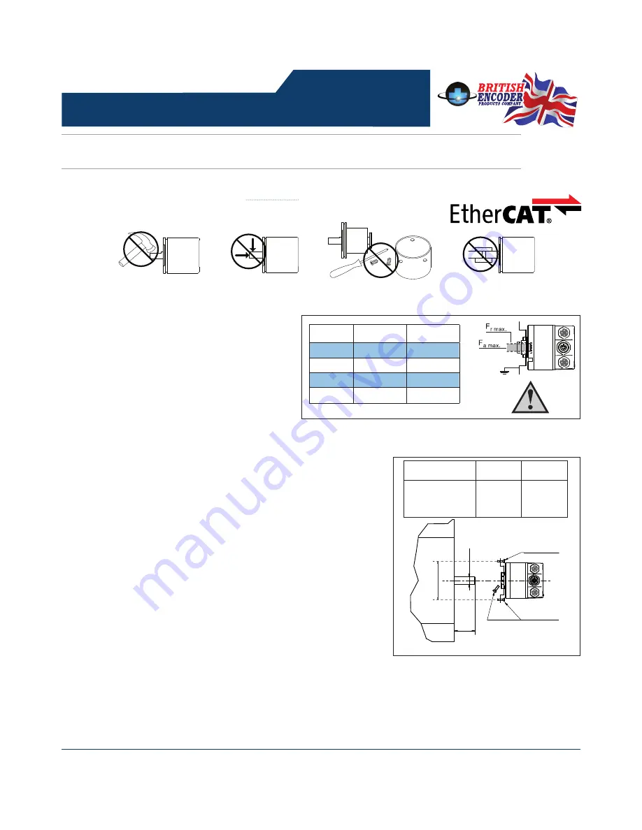
Do not shock or strike.
Do not subject shaft to excessive
axial or radial shaft stresses.
Do not use a rigid coupling.
Do not disassemble.
Hollow Bore Mounting
63
M3 (8.8)
M3 (8.8)
Ma = 1 Nm
Diameter (D)
L
min
L
max
6, 7, 8, 10, 12 14
or 15 mm and
0.250” and 0.375”
10 mm
19 mm
D
L-
Standard F
r
max.
F
a
max.
Ø 6 mm
125 N (28.1 lb)
120 N (26.9 lb)
Ø 8 mm
125 N (28.1 lb)
120 N (26.9 lb)
Ø 10 mm
220 N (49.4 lb)
120 N (26.9 lb)
Ø 0.375”
220 N (49.4 lb)
120 N (26.9 lb)


