Bose AHX-32-0, Owner'S Manual
The Bose AHX-32-0 Owner's Manual is a comprehensive guide for users, providing detailed instructions for optimal product usage. Download this manual for free from our website and gain access to all the necessary information to enhance your experience with the Bose AHX-32-0.
Share
Download


Reviews:
No comments
Related manuals for AHX-32-0
ONE
Brand: XBOX Pages: 13

CHSPBTSPKBLK
Brand: Conceptronic Pages: 17

SE-2RPTT
Brand: Sigtronics Pages: 2

RZ04-0346
Brand: Razer Pages: 19

VOYAGER 520
Brand: Plantronics Pages: 17
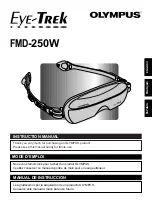
Eye-Trek FMD-250W
Brand: Olympus Pages: 31

Peltor WS ProTac XPI
Brand: 3M Pages: 260
VA2
Brand: Exibel Pages: 5

M50
Brand: Plantronics Pages: 2

PERFORM 45
Brand: Jabra Pages: 19

SH-40
Brand: Sigtronics Pages: 2

HS 2700 BT
Brand: Silvercrest Pages: 9

367103 2101
Brand: Silvercrest Pages: 61

KH 2356
Brand: Silvercrest Pages: 68

BTST-9300
Brand: Silvercrest Pages: 86

281659
Brand: Silvercrest Pages: 212

WH-CH400
Brand: Sony Pages: 2

WF-SP700N
Brand: Sony Pages: 89


