Blue Seal Evolution G592, Service Manual
The Blue Seal Evolution G592 is a top-of-the-line commercial oven that will revolutionize your cooking experience. To ensure optimal usage, make sure to download the free Installation and Operator's Manual from our website. This comprehensive manual provides step-by-step instructions and troubleshooting tips for an exceptional cooking performance.
Share
Download


Reviews:
No comments
Related manuals for Evolution G592
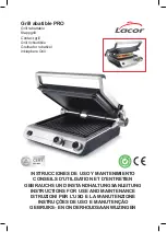
PRO
Brand: Lacor Pages: 88

ASCD18W2
Brand: Fein Pages: 52

ASCT18
Brand: Fein Pages: 133

ABS18 Q
Brand: Fein Pages: 70

FP710
Brand: Feider Machines Pages: 12

Epicure EOG36
Brand: Dacor Pages: 16

BP-2973
Brand: TriStar Pages: 40

DD 200
Brand: Hilti Pages: 344

CW-74ET
Brand: Lotus cooker Pages: 26

E-420
Brand: Summit Pages: 76

R18AD
Brand: Ryobi Pages: 8

42.589.98
Brand: EINHELL Pages: 32

EX-335
Brand: Weber Pages: 48

PT11
Brand: bora Pages: 24

CBC1465WB-U
Brand: Uniflame Pages: 12

Spinnit FMM-3
Brand: Lassco Wizer Pages: 25

BILEX730
Brand: Napoleon Pages: 32

YT-82780
Brand: YATO Pages: 100


