


Instruction Manual Book
Made in Vietnam.
Item code: BH113-A.
Wingspan: 1,671mm (65.79in).
Length: 1,620mm (63.78in).
Weight: 4.8kg (10.56lbs).
Wing area: 53dm
2
.
Wing loading: 90g/dm
2
.
Wing type: Naca Airfoil.
Gear type: Mechanic retract
with oleo struts
(included).
Parts listing required (not included)
.
Radio: 08 channels.
Servo: 08 servos. Size: (42x21)mm.
+2 servos retract. Size: (35.1x16x25.9)mm.
SPECIFICATION
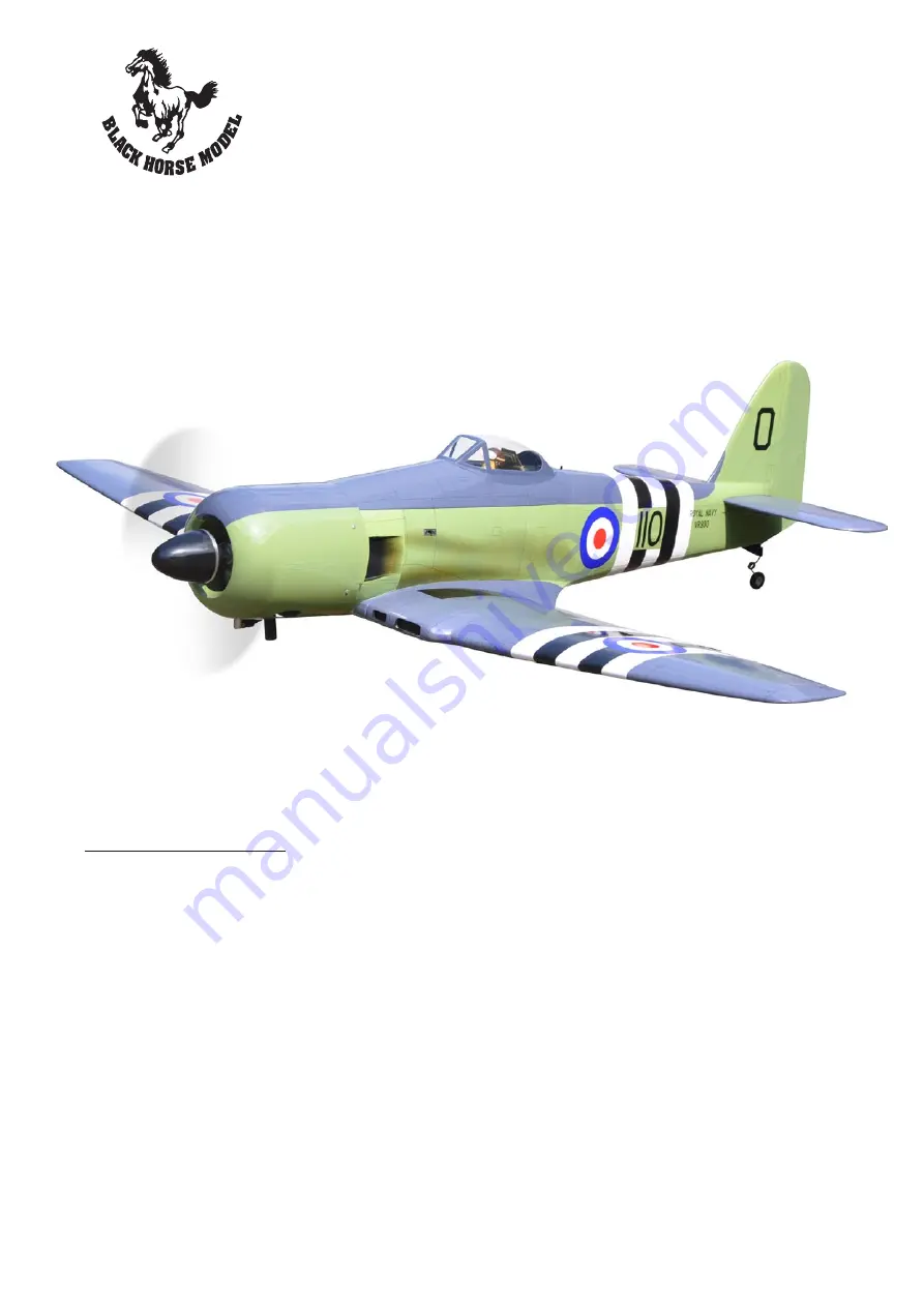
SEA FURY
Engine: 20-22cc Gas.
Motor: Brushless outrunner 1800-2300W, 450KV.
Propeller: Suit with your engine.
Recommended motor and battery set up (not included):
Motor: RIMFIRE.120.
Lipo cell: 6 cells 4,000-5,000mAh.
ESC: 80A.
Receiver battery: 4.8-6V/ 1200-2000mAh NiMH.
Servos retracts (FUTABA, S3170G).
New improvement.
95% ALMOST READY TO FLY
ALL BALSA - PLY WOOD CONSTRUCTION.
COVERED IN A HEAT-SHRINK FILM WITH PRINTED.


