


CUSTOMER SUPPORT INFORMATION
Order
toll-free
in the U.S.: Call
877-877-BBOX
(outside U.S. call
724-746-5500
)
FREE technical support 24 hours a day, 7 days a week: Call
724-746-5500
or fax
724-746-0746
Mailing address:
Black Box Corporation
, 1000 Park Drive, Lawrence, PA 15055-1018
Web site:
www.blackbox.com
• E-mail:
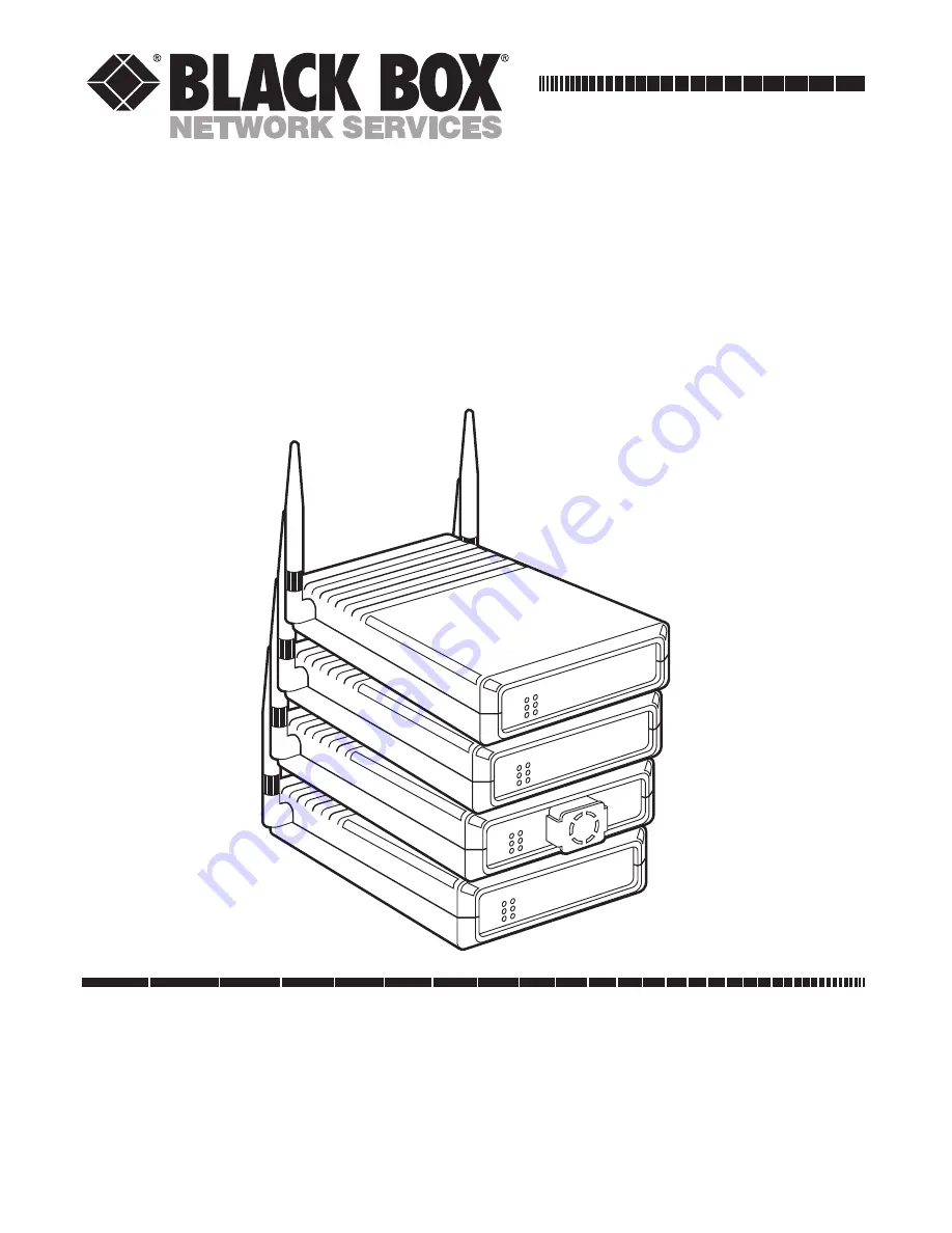
PWR
WLNK
ETHR
H
M
L
QLT
Wireless
Bridge
PWR
WLNK
ETHR
H
M
L
QLT
PWR
WLNK
ETHR
H
M
L
QLT
Workstation
Adapter
PWR
INFR
ETHR
H
M
L
LOAD
Wireless
Ethernet Hub
3-Mbps Wireless Ethernet
Hubs, Adapters, and Bridges
FEBRUARY 1998
LW001A LW004A
LW008A
LW011A
LW002A LW005A
LW009A
LW011AE
LW003A LW007A
LW010A
LW012A
LW012AE


