Black Box ACU8000A, Manual
The Black Box ACU8000A is a versatile and powerful cooling unit designed to meet your cooling needs. With its easy-to-use interface and advanced features, this product ensures optimal performance. Download the free user manual from our website to unlock the full potential of your ACU8000A and maximize its cooling capabilities.
Share
Download


Reviews:
No comments
Related manuals for ACU8000A
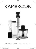
KSB655
Brand: Kambrook Pages: 20
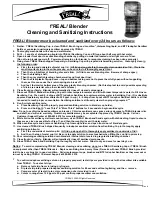
Blender
Brand: F'real Pages: 2

Multiquick 7 MR 700
Brand: Braun Pages: 50

CAT5 ClassWork Plus Multiloop
Brand: Black Box Pages: 12

FB500
Brand: Back to Basics Pages: 48

IR Link Series
Brand: Ebode Pages: 28

perfectsignal
Brand: Post Pages: 13

DC-LINK-ULR1
Brand: DwarfConnection Pages: 2

Matrixline 2000 Series
Brand: KVM-TEC Pages: 55
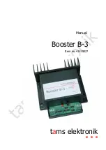
40-19327
Brand: tams elektronik Pages: 24

AD 4076
Brand: Adler Europe Pages: 68

TSA3510
Brand: Teesa Pages: 28

OSD Pro
Brand: Eagle Tree Systems Pages: 18

LPR1101
Brand: Black Box Pages: 1

TM5010
Brand: Concept2 Pages: 69

LM-HE150
Brand: LINK-MI Pages: 5

Linksys RE1000
Brand: Cisco Pages: 2

RE500X
Brand: TP-Link Pages: 2


