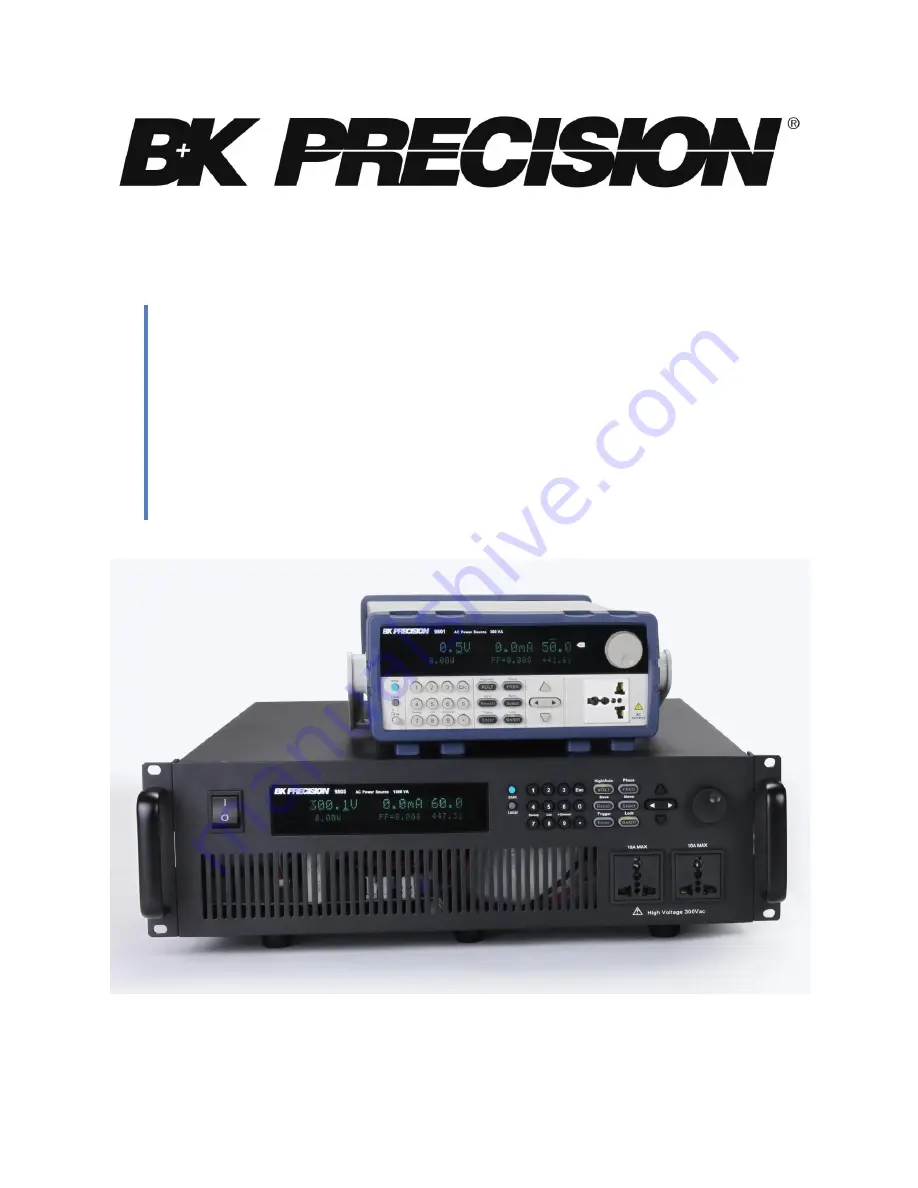
background image


9800 Series


Programmable AC Power Source 
Models: 9801, 9803, 9805 

USER MANUAL 

Summary of Contents for 9801

Page 1: ...9800 Series Programmable AC Power Source Models 9801 9803 9805 USER MANUAL...

Page 2: ...ctrical energy available and the voltage impulses that may occur on electrical conductors associated with these category ratings The category rating is a Roman numeral of I II III or IV This rating is...

Page 3: ...Ground the Instrument To minimize shock hazard the instrument chassis and cabinet must be connected to an electrical safety ground This instrument is grounded through the ground conductor of the suppl...

Page 4: ...w even if the air temperatures are within specifications In direct sunlight This instrument is intended to be used in an indoor pollution degree 2 environment The operating temperature range is 0 C to...

Page 5: ...s even with the power cord removed dangerous voltages may exist when the covers are removed To avoid injuries always disconnect the power cord from the instrument disconnect all other connections for...

Page 6: ...nd performance features are maintained Cooling fans This instrument contains one or more cooling fans For continued safe operation of the instrument the air inlet and exhaust openings for these fans m...

Page 7: ...instrument Do not obstruct cooling air flow to the instrument Do not place a hot soldering iron on the instrument Do not pull the instrument with the power cord connected probe or connected test lead...

Page 8: ...C of the European Parliament and the Council of the European Union on waste electrical and electronic equipment WEEE and in jurisdictions adopting that Directive is marked as being put on the market a...

Page 9: ...ents of 2006 95 EC Low Voltage Directive and 2004 108 EC Electromagnetic Compatibility Directive with the following standards Low Voltage Directive EN61010 1 2001 EMC Directive EN 61000 3 2 2006 EN 61...

Page 10: ...ins connect disconnect switch on the front of the instrument DC current Alternating current Fuse Symbol Chassis earth ground symbol Ground terminal Protective earth ground CAUTION indicates a hazardou...

Page 11: ...erview 7 Display Description 8 2 Getting Started 9 2 1 Input Power and Fuse Requirements 9 Input Power 9 Fuse Requirements 11 Fuse Replacement 12 2 2 Input Connections 15 2 3 Output Connections 16 2 4...

Page 12: ...Voltage Limits 31 Frequency Limits 32 Current Protection 33 External BNC 33 3 5 Dimmer Output Simulation 35 3 6 List Mode 36 Configure List Setting 37 Edit List File 38 Recall and Run Program 40 Powe...

Page 13: ...3 5 Troubleshooting Guide 47 General 47 Remote Control 48 6 Specifications 49 Calibration 50 SERVICE INFORMATION 51 LIMITED TWO YEAR WARRANTY 52...

Page 14: ...2 LAN and GPIB model 9803 and 9805 only Power line disturbance simulation Dimmer output simulation Adjustable output phase Frequency and voltage sweep function List mode to generate surge sag and othe...

Page 15: ...recision 1 3 Product Dimensions 9801 The 9801 power supply is designed to fit in a standard 19 inch half rackmount optional IT E151 rackmount kit and is of 2U size Figure 1 Front Panel View Figure 2 R...

Page 16: ...3 Figure 3 Side View 9803 and 9805 The 9803 and 9805 power supplies are designed to fit into a standard 19 inch rackmount and is of 3U size Figure 4 Front View...

Page 17: ...4 Figure 5 Side View 1 4 Front Panel Overview Figure 6 Front Panel 9801 1 2 3 5 4...

Page 18: ...t the instrument back to local mode Shift button Enables access to secondary functions of some buttons Esc button Used to exit menu settings VOLT High Auto button Set the output voltage or range betwe...

Page 19: ...hanges or to send a trigger manually On Off On Off Lock button Controls the output state or locks the front panel button Navigation arrow keys 1 5 Rear Panel Overview Figure 8 Rear Panel 9801 Figure 9...

Page 20: ...and other functionality see External BNC section AC Output Terminal Cooling Fans AC Input Fuse Box GPIB Interface System Bus not used Line Voltage Selector 1 6 Display Overview 8 7 6 5 4 3 2 1 300 0V...

Page 21: ...te mode SQR Indicates service request Error Indicates an error has occurred Trig Indicates waiting for trigger for list operation Prot Indicates protection trip for over voltage or over temperature Au...

Page 22: ...rument has the following input power requirements 9801 AC Voltage 110 V 10 or 220 V 10 Frequency 47 Hz 63 Hz 9803 and 9805 AC Voltage 110 V 10 or 220 V 10 Frequency 47 Hz 63 Hz Use the line voltage se...

Page 23: ...the Fuse Requirements section for details on changing the fuse Disconnect all cables including the power cord from the instrument when changing the instrument s line voltage After changing the line vo...

Page 24: ...at it can meet the required power ratings for this instrument Any misuse with wrong or unsafe cables will void the warranty Fuse Requirements An AC input fuse is necessary when powering the instrument...

Page 25: ...pull and slide out the fuse box as indicated below 4 Pull out the fuse inside to check and or replace if necessary for the desired line voltage operation 5 Insert the fuse in the same location 6 The...

Page 26: ...13 Figure 14 Removing top cover 3 Remove the top cover of the power supply...

Page 27: ...AC Input Fuse Table 6 Insert the fuses in the same location 7 The fuses will now be locked and secured 8 Place back the top cover over the instrument and install all the screws before operation Disco...

Page 28: ...a reliable and proper AC input connection and refer to reference setup Check both ends of the power cord are disconnected from everything before connecting it to the AC input terminal DO NOT make a co...

Page 29: ...AC input terminal cover over the input terminal and secure the two screws Gently pull the cover and the power cord afterwards to ensure that both are secured to the instrument 2 3 Output Connections T...

Page 30: ...wer supply To protect personnel against accidental contact with hazardous voltages ensure that the load and its connections have no accessible live parts Ensure that the load wiring insulation rating...

Page 31: ...e type of wires to use Step 3 Place the three wire ends through the output terminal Make note of the wires and ensure the proper color wire is connected to the right terminal i e In the US Green yello...

Page 32: ...ater than to the maximum output voltage of the power supply AWG 6 8 10 12 14 16 18 20 22 Imax A 75 55 40 25 20 13 10 7 5 m meter 1 3 2 1 3 3 5 2 8 3 13 2 21 33 5 52 8 Table 2 Wire Gauge Rating 2 4 Pre...

Page 33: ...d or the rotary knob enter a voltage value The voltage display will show the value you entered If entering with the numeric keypad press first then enter the value and press Enter Enter 3 Press the bu...

Page 34: ...l frequency range is within specifications Check Model and Firmware Version The model and firmware version can be verified by using the IDN query remote command It can also be found from within the me...

Page 35: ...tection setting BNC Set Select external BNC connection setup Ipeak Protect Configures current peak protection point Dimmer Configures dimmer output function List Set Configure list start trigger Meas...

Page 36: ...quency and phase can be set from the front panel Setting Voltage The user has the ability to set the voltage within the range of 0 0 V to 300 0 V in all three units When the button is pressed the butt...

Page 37: ...e the output to protect the instrument and DUT device under test from potential damage Setting Frequency The user has the ability to set the frequency within the range of 45 0 Hz to 500 Hz When the bu...

Page 38: ...t Use the numeric keys to set the stop phase angle and press Enter Enter to confirm the stop phase setting 3 3 SYSTEM Menu All setup procedures and settings explained in this section can be accessed f...

Page 39: ...e factory default settings Table 3 Factory Default Settings Voltage 0 0 V Frequency 50 0 Hz Start Phase 0 0 Stop Phase 0 0 Range Auto Power Out Setting Off Power On Setting Sav0 Key Sound ON Trigger S...

Page 40: ...tput state of the power supply can be configured to either off or the last state of the output before power down Follow the steps below to configure this option 1 From the SYSTEM menu select Power Out...

Page 41: ...lable for remote communication USBTMC RS 232 and LAN are standard for all units GPIB is available on the 9803 and 9805 units only This section will describe how to setup all the supported interfaces N...

Page 42: ...select Communication and press Enter Enter 2 Select USB and press Enter Enter to set to USBTMC for remote communication 3 Install the USB driver on to your PC For Windows 7 or later users this may in...

Page 43: ...mmunication 2 Use the keys to select Address 0 31 and press the Enter Enter button 3 To exit the menu at any time press the key three times Save Recall Instrument Settings The instrument can save up t...

Page 44: ...n press 5 to recall settings in location 5 immediately 4 To exit Recall mode press Recall and it will no longer be illuminated The cursor on the display will reappear indicating that the instrument is...

Page 45: ...mum and frequency maximum limits This feature limits the user from entering a frequency setting outside of these limits For example if Freq Min is set for 50 Hz and Freq Max is set for 60 Hz the unit...

Page 46: ...e output as soon as a continuous current exceeds the current setting Delayed shutoff will shut off the output with about a 1 second delay when the continuous current exceeds the current setting 4 To e...

Page 47: ...l TTL logic signal is sent The instrument triggers off a falling edge from logic high 5 V to low 0 V A negative TTL level pulse signal with pulse width 50 s can be used as a trigger as illustrated bel...

Page 48: ...output O On Selecting this option will configure the BNC port as an output to monitor the state of the AC output A 5 V TTL logic high signal means the output is ON A 0 V TTL logic low signal means the...

Page 49: ...ion with trailing edge selected To change the phase angle see the instructions below Off Disables the dimmer function 3 To exit the menu at any time press twice Note If the dimmer function is enabled...

Page 50: ...At the start of a list program there is a 50 ms delay in which the power supply will output 0 V before it begins outputting according to the parameters in the first step of the list Configure List Set...

Page 51: ...tage 0 0 V 300 0 V Frequency Setting Sets the step s frequency 45 0 Hz 500 Hz Slope Sets the slope time to the next step 0 0 s 999 9 s Dwell Units Sets the unit for the step width Second Minute Hour D...

Page 52: ...mpleted of the first step before the first PLD occurs If the first step s dwell time is set to the minimum of 0 1 s then 200 ms of the first step will output instead before the first PLD occurs Therea...

Page 53: ...ss and will return back to the LIST menu Run Program To run a program list after it is recalled the trigger source must be configured first Refer to Configure List Setting to set up the trigger source...

Page 54: ...al for details If the Trigger Source is configured to Extern then use the external BNC to trigger the list Power Line Disturbance Simulation PLD In list mode the user has the ability to enable or disa...

Page 55: ...ep frequency and step time The step time may be indicated in seconds minutes or hours Once the sweep starts the power supply will cycle through the voltage steps from initial to final voltages startin...

Page 56: ...To access the edit list menu press Shift and press 7 Sweep Now select the Edit option and press Enter Enter The adjustable range and operation for each of the sweep parameters are specified in table b...

Page 57: ...stored in Select a number between 0 to 9 with the rotary knob or the numeric keypad then press Enter Enter 3 Once selected the display will read Recall Data Success and will return back to the SWEEP m...

Page 58: ...Key Lock The front panel keys can be locked to prevent unwanted changes to output settings and power supply configurations Follow the steps below to enable disable key lock 1 Press Shift and Lock On...

Page 59: ...r crossover DB9 serial cable USB The instrument has a USB interface USBTMC on the rear panel for remote communication To select this interface to communicate with the unit please see Communication Set...

Page 60: ...g manual for details which can be downloaded from www bkprecision com 5 Troubleshooting Guide Below are some frequently asked questions and answers Please check if any apply to your power supply befor...

Page 61: ...likely the result of the phase being cut which results in a distorted waveform This also leads to less RMS voltage See the Dimmer Output Simulation section for more information Remote Control Q I am...

Page 62: ...5 at 45 500 Hz Resistive Load Line Regulation 0 1 max for a 10 line change Load Regulation 0 5 FS Resistive Load Response Time 100 s Programming Voltage rms Range 0 300 V 150 300 V Auto Resolution 0 1...

Page 63: ...5 only Operating Environment 0 40 C 20 80 RH Dimensions W H D mm 214 5 88 2 453 5 439 x 131 4 x 535 7 439 x 131 4 x 535 7 Weight 9 5 kg 40 kg 52 2 kg The current range switches from low to mid range o...

Page 64: ...probes connectors and accessories that you are using with the device Customers not on an open account must include payment in the form of a money order or credit card For the most current repair char...

Page 65: ...strument via our website www bkprecision com Exclusions This warranty does not apply in the event of misuse or abuse of the product or as a result of unauthorized alterations or repairs The warranty i...

Page 66: ...22820 Savi Ranch Parkway Yorba Linda CA 92887 www bkprecision com 2017 B K Precision Corp Printed in China v020217...

Reviews: