


ALGAS-QA
Instruction and Operation Manual
© Copyright by BIFFI Italia. All right reserved
page 1
Contents may change without notice
Instruction and Operation Manual
ALGAS-QA
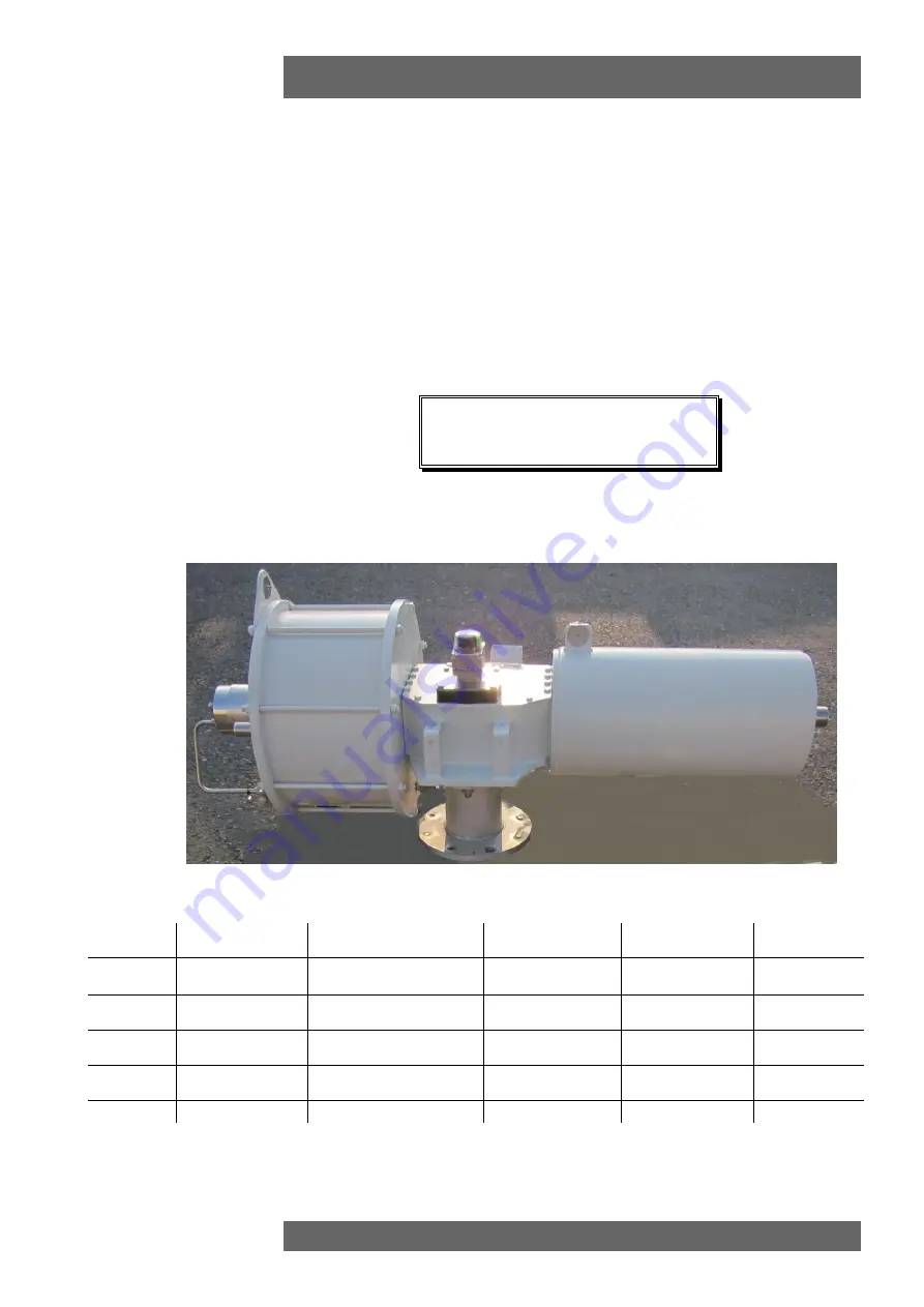
“QUICK ACTING”
SPRING
RETURN PNEUMATIC
ACTUATOR
MAN 616
4
21/03/18
Updated Data-plate
Ermanni
Orefici
Vigliano
3
18/04/16
Updated applicable
regulation (chapter 1.1.1)
Ermanni
Orefici
Vigliano
2
29/03/13
General update
Ermanni
Stoto
Vigliano
1
20/12/05
Updated document
Ermanni
Stoto
Vigliano
0
05/05/99
Document release
Lazzarini
Aliani
Ziveri
Rev.
Date
Description
Prepared
Checked
Approved


