Better Water MediPac, Operator'S Manual
Download the free Operator's Manual for the Better Water MediPac, an innovative product designed to provide clean and refreshing water. Enhance your understanding of the product's features, installation process, and maintenance requirements by visiting manualshive.com and accessing the manual.
Share
Download


Reviews:
No comments
Related manuals for MediPac

PWSYS-UF-KC3
Brand: Watts Pages: 8

AXESS 180
Brand: salmson Pages: 16

DV 300-PA
Brand: Giebel Pages: 8

RL14
Brand: red lion Pages: 8

6-180041
Brand: BWT Pages: 52

160197
Brand: Aqua Flo Pages: 4

RS3000R
Brand: PurePro Pages: 4

NSVS1104
Brand: JRC Pages: 4

Space-ette FHD700 5 1G
Brand: Drinking Fountain Doctor Pages: 4

PBX-CAB-DOS
Brand: Clean Logix Pages: 13

PRO 1000
Brand: BS POOL Pages: 39

Five Water Maker WM5-50
Brand: Nimbus Water Systems Pages: 14

AFS Systems
Brand: Advantage Controls Pages: 8

LARYVOX TOUCH HME
Brand: Fahl Pages: 52
880635
Brand: YAMADA Pages: 16
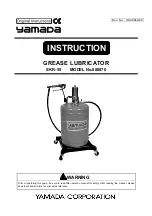
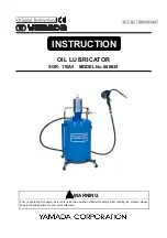
SKR-55 880870
Brand: YAMADA Pages: 18

SKR-110A50
Brand: YAMADA Pages: 18

SKR110A50PAL
Brand: YAMADA Pages: 20


