background image


1645 Lemonwood Dr. 

Santa Paula, CA  93060  USA 

Toll Free: (800) 253-2363 

Telephone: (805) 933-9970 
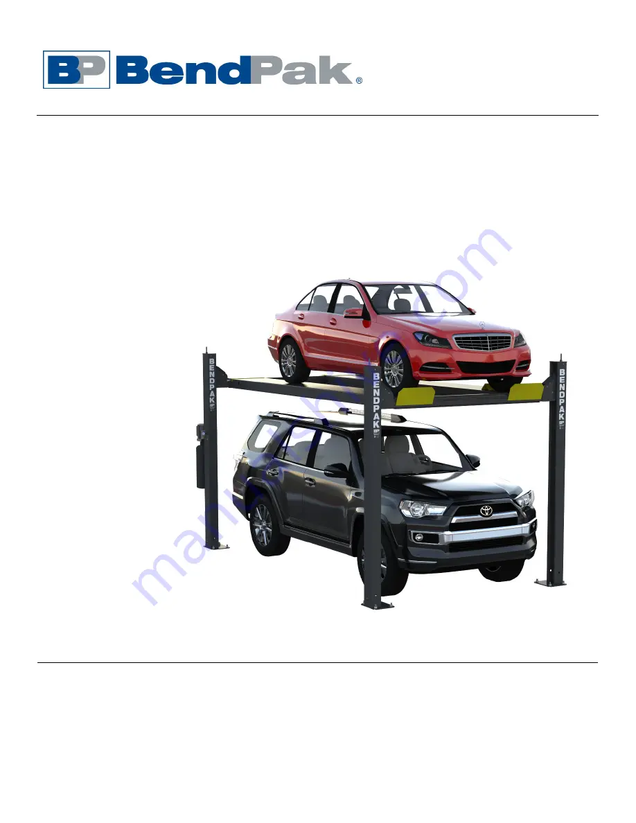
bendpak.com


Four-Post Lifts 

Installation and Operation Manual 

Manual P/N 5900041 — Manual Revision M — July 2019 


Models: 


HD-7P 


HD-7W 


Designed and engineered by BendPak Inc. in Southern California, USA. Made in China. 


DANGER


Read the 

entire contents

 of this manual 

before

 using this 

product. Failure to follow the instructions and safety precautions in 
this manual can result in serious injury or death. Make sure all other 
operators also read this manual. Keep the manual near the product 
for future reference. By proceeding with installation and operation, 
you agree that you fully understand the contents of this manual.


Summary of Contents for HD-7P

Page 1: ...dPak Inc in Southern California USA Made in China DANGER Read the entire contents of this manual before using this product Failure to follow the instructions and safety precautions in this manual can result in serious injury or death Make sure all other operators also read this manual Keep the manual near the product for future reference By proceeding with installation and operation you agree that...

Page 2: ... to bendpak com support register your product and fill out the online form to register your product be sure to click Submit Safety Your product was designed and manufactured with safety in mind However your safety also depends on proper training and thoughtful operation Do not install operate maintain or repair the unit without reading and understanding this manual and the labels on the unit do no...

Page 3: ...erating maintaining or repairing this equipment failure to do so could result in property damage product damage injury or in very rare cases death Make sure only authorized personnel operate this equipment All repairs must be performed by an authorized technician Do not make modifications to the unit this voids the warranty and increases the chances of injury or property damage Make sure to read a...

Page 4: ... entire manual carefully before installing or using the product Do not install or operate the product until you are familiar with all operating instructions and warnings Do not allow anyone else to operate it until they are familiar with all operating instructions and warnings Keep this manual on or near the product for future reference Read and follow the warnings and instructions on the labels o...

Page 5: ...ifications to the equipment without prior written permission from BendPak Damage to the equipment from external influences Incorrect operation of the equipment Electrical Information DANGER All wiring must be performed by a licensed certified Electrician Do not perform any maintenance until main electrical power has been disconnected from the Lift and cannot be re energized until all procedures ar...

Page 6: ...r the Runways are routed through the Crosstubes The Crosstubes are not the same each Crosstube has an opening called a Window that faces the inside orienting the Windows correctly is described in the Installation section Windows must be installed so that they open to the inside of the Lift Lifting Cables go into the Crosstubes through the Windows Ramps One for each Runway Use them to drive onto an...

Page 7: ...k website for more information Air Line Kit Optional product that provides the infrastructure to get air to your Rolling Jacks conveniently routing the air lines under the Lift s Runways Refer to the Air Line Kit page on the BendPak website for more information WSA 100 Utility Station Optional product that adds air and electric outlets to your Lift Refer to the WSA 100 Utility Station page on the ...

Page 8: ...HD 7P HD 7W Four Post Lifts 8 P N 5900041 Rev M July 2019 Specifications ...

Page 9: ... mm 38 963 mm or 44 25 1 121 mm m Runway Centerline 56 5 1 437 mm 56 5 1 437 mm or 63 5 1 610 mm n Outside Edge of Runways 75 5 1 919 mm 75 5 1 919 mm or 82 5 2 092 mm Min Wheelbase rated capacity 1 115 2 921 mm Min Wheelbase 75 capacity 1 100 2 540 mm Min Wheelbase 50 capacity 1 85 2 159 mm Min Wheelbase 25 capacity 1 70 1 778 mm Locking Positions 17 spaced every 4 102 mm Lifting time 35 seconds ...

Page 10: ...le BendPak strongly recommends measuring Q Does it matter if I drive my Vehicles in front first or back them in A We recommend driving your Vehicle in front first because that makes it easier to center the wheels on the Runways But it is up to you the Lift works great either way Also remember to put the Front wheels up against the Tire Stops and chock the Rear wheels Q Will the Lifting Cables real...

Page 11: ... Ladders 16 Remove the Sheaves 17 Install the Runways 18 Install the first end of the Flex Tube 19 Route the Lifting Cables 20 Working with Compression Fittings and Tubing 21 Install the Air Lines 22 Install the Hydraulic Hose 23 Install the Return Line 24 Install the Power Unit 25 Install the second end of the Flex Tube 26 Install the Pushbutton Air Valve and connect the Air Line 27 Connect the R...

Page 12: ...eading and understanding this manual and the safety labels on the unit Only fully trained personnel should be involved in installing this equipment Pay attention at all times Use appropriate tools and lifting equipment Stay clear of moving parts BendPak recommends referring to the current version of the ANSI ALI ALIS Standard Safety Requirements for Installation and Service for more information ab...

Page 13: ...cord with appropriate plug to the electrical box on the Lift for connection to a power outlet or have them wire it directly into the electrical system at the Lift location Note that installing the Power Unit and connecting the Power Unit to the power source are separate procedures and are done at different times in the installation process You do not need an Electrician to install the Power Unit b...

Page 14: ...and Tire Stops go on the Lift and the Front and Rear of the Lift Selecting an Approach does not impact your Power Post location choice In many cases selecting an Approach is easy the garage shop has walls on three sides and an open door on the fourth side The open door is the Approach side If your location has an open door on both ends pick one side to be the Approach side install your Ramps on th...

Page 15: ...ear of the Lift are It does impact other aspects of the installation however You have two options for Power Post location Driver Side Front or Passenger Side Rear Drawing not necessarily to scale Not all components shown Powerside Runway which has the Hydraulic Cylinder under it must be installed next to the Power Post no matter which Power Post location you choose Most customers choose their Powe...

Page 16: ...ur Post Lifts 16 P N 5900041 Rev M July 2019 Checking Clearances For safety purposes a certain amount of clear space around the Lift is required Drawing is a top view Not necessarily to scale Not all components shown ...

Page 17: ...oor level or using a different location Shimming If your Concrete floor is not completely level you can use Shims under the bases of the Posts as needed to level the Lift To estimate your Shim requirements use a transit level and targets to check for flatness Use the provided Shims as necessary NOTICE Do not shim a Post more than half an inch using the provided Shims and Anchor Bolts A maximum shi...

Page 18: ...u are CAUTION Some Lift components are very heavy if handled incorrectly they can damage materials like tile sandstone and brick Try to handle the Lift components twice once when delivered and once when moved into position You must have a Forklift or Shop Crane to move them into position Use care when moving them WARNING The Posts and Runways are delivered with stabilizing structures on each end B...

Page 19: ... fit into the four corners created by the Chalk Line Guides Refer to Specifications to determine the Overall Width and Outside Length values for your Lift Note Do not use the Overall Length value this includes the Ramps which are not taken into consideration for creating Chalk Line Guides Drawing is a top view Not necessarily to scale Not all components shown ...

Page 20: ...gth setting The side Chalk Lines must be parallel to each other Measure to verify that they are parallel 3 Create the Rear Chalk Line parallel to the Front Chalk Line Make the Rear Chalk Line longer than the Overall Width setting for your Lift model The Front and Rear Chalk Lines must also be parallel to each other Measure to verify that they are parallel 4 Before moving the Posts into position me...

Page 21: ...ier The other three Posts can go at any of the remaining Post locations 2 Stand up each Post Have at least two people work together to stand up a Post WARNING Be very careful when walking around the Posts they are not anchored down at this point so it is possible to knock them over which could cause significant injury 3 Orient each Post as you stand it up The inside where the Lift Head is of each ...

Page 22: ...e first time Both Crosstubes must be installed so that the Windows open to the inside of the Lift Important Your Power Post location impacts Crosstube installation The Crosstube with two Small Windows must be installed next to the Power Post The location of the Ramps do not come into play when determining where the Crosstubes get installed Crosstubes must be installed so that their Windows are on ...

Page 23: ...Crane raise a Crosstube above the top of the two Posts that it goes between then slide the Crosstube down into place 3 Perform Step 2 for the second Crosstube About Slide Blocks The black Slide Blocks in the corners of the ends of the Crosstubes come installed from the factory If they fall off or do not come installed put them into place so that each pair creates a Slot into which the Ladder for e...

Page 24: ... Safety Locks share the Safety Lock holes WARNING Safety Locks are dependent on correct installation of the Ladders Pay careful attention when installing the Ladders If they not installed correctly the Lift may not be able to hold the weight of a Vehicle which could fall and damage the Vehicle or the Lift or cause harm to any persons in the area The Ladders are steel pieces with holes spaced every...

Page 25: ... the bottom of the Ladders once the Crosstubes have been raised so that portion of installing the Ladders is described in Securing the Ladders Each Ladder has 17 holes in it spaced four inches apart these holes are for the Safety Locks Each Ladder has a Bolt Hole at the bottom and a Threaded Bolt at the top WARNING Make sure to install the Ladders correctly If they are not installed correctly the ...

Page 26: ...all four Ladders go through both Slots created by the Slide Blocks 2 Install the other three Ladders the same way 3 Moving to the top of the Ladders move the Stop Nut half of the way down towards the top of the Ladder 4 Put a Top Cap onto the top of the Post put the Threaded Bolt on the top of the Ladder through the appropriate hole put the tabs on the side of the Top Cap inside the Post and secur...

Page 27: ...Slack Safety Locks will automatically engage when you raise the Crosstubes They cannot be engaged as you continue with the installation so they must be disengaged 2 To disengage the Slack Safety Locks after raising a Crosstube raise and hold one end of a Crosstube so the Primary and Slack Safety Locks are disengaged push and hold the Sheave or the Steel Piece in towards the Ladder and the back of ...

Page 28: ... the Post 5 Take the second Washer and the Nut and install them on the end of the Bolt secure the Nut 6 Perform the same procedure to secure the other three Ladders on the Lift Note Do not securely tighten the Top Nut at the top of the Top Cap at this point The Top Nut and the Stop Nut will be used later to make sure the Lift is level They can be securely tightened after you do the final leveling ...

Page 29: ...able Sheaves on the underside of the Powerside Runway the two Side Sheaves and the four Gusset Sheaves and their Lock Pins When you remove the Sheaves keep all of the components together You will be reinstalling them at the same location using the same components Not necessarily to scale Not all components shown Combines top and side views ...

Page 30: ...er it Orient the two Runways this way Utility Rails on the inside Find the Powerside Runway by looking under the two Runways only the Powerside Runway has a Hydraulic Cylinder underneath it and put it next to the Power Post There is also an 1 5 inch wide hole in the outside of the Powerside Runway near the Power Post There are other holes in the Runways but they are smaller and used with accessori...

Page 31: ...ed 3 Use a Forklift or Shop Crane to pick up the Powerside Runway and move it into place on the Powerside of the Lift Make sure the Utility Rail is on the inside 4 Bolt the Powerside Runway into place two Bolts on each end going into the Crosstubes 5 Using a Forklift or Shop Crane pick up the Offside Runway and move it into place Make sure the Utility Rail is on the inside 6 Bolt the Offside Runwa...

Page 32: ...s done after the Runways are installed now the second part after the Power Unit and the Flex Tube Bracket Plate is installed later The following drawing shows the Flex Tube Not necessarily to scale Not all components shown To install the Flex Tube to the Powerside Runway 1 Unscrew the Plastic Nut from one end of the Flex Tube It does not matter which end you use 2 Holding the Flex Tube by the Plas...

Page 33: ...ther end of the Powerside Runway adjacent to the Small Windows There are four Gusset Sheaves one in each Crosstube Gusset each has a Lock Pin that also needs to be removed There are two Side Sheaves one on each side of the Powerside Runway All Sheaves come installed They should have been removed earlier in the installation process just before installing the Runways If any of the Sheaves are still ...

Page 34: ...HD 7P HD 7W Four Post Lifts 34 P N 5900041 Rev M July 2019 The following drawing shows the components involved in routing the Lifting Cables Not necessarily to scale Not all components shown ...

Page 35: ...HD 7P HD 7W Four Post Lifts 35 P N 5900041 Rev M July 2019 Not necessarily to scale Not all components shown ...

Page 36: ... you removed before you installed the Runways Use the drawings on the previous two pages in conjunction with this procedure To route Lifting Cables A and C 1 Starting with Lifting Cable A move the entire thing to just under the Large Window it goes through near the bottom of Post A Check the label to make sure you have the correct Lifting Cable 2 Remove the Nut and Washer from the Threaded End if ...

Page 37: ...ng We will securely tighten all four Nuts later in the installation procedure Note The Threaded end of Lifting Cable A should go just a little bit through the Top Cap If it is way too long or way too short you probably have the wrong Lifting Cable If it is just a few inches short then the Piston on the Hydraulic Cylinder may not have been pulled out far enough 8 Make sure the Button End and the un...

Page 38: ... of the Cable Anchor Plate shown below Not necessarily to scale Not all components shown 17 Gather the unrouted portions of Lifting Cables A and C making sure to orient Lifting Cable C above Lifting Cable A 18 Push Lifting Cables A and C into the space where the double Cable Sheave goes in the Large Window and move the Button Ends towards the Pull Box Not necessarily to scale Not all components sh...

Page 39: ...e Button Ends of both Lifting Cables A and C towards the Cable Anchor Plate on the side of the Runway 24 Unscrew the Bolts at the bottom of the Cable Anchor Plate slide the Lifting Cables into position in the Cable Anchor Plate in the Gap over the L section back up against the Cable Anchor Plate and with C on top and A on the bottom and then reinstall the Bolts Not necessarily to scale Not all com...

Page 40: ...heave already is If the Cable is not in this exact location the Slack Safeties will not work correctly later on 5 Reinstall the Gusset Sheave and the Cable Lock Pin in Post B 6 Double check to make sure Lifting Cable B is correctly positioned in the Gusset Sheave between the Gusset Sheave and the Slack Safety Sheave with the Cable Lock Pin under it 7 Push the Threaded End of Lifting Cable B up to ...

Page 41: ...e Pull Box 21 Put both Lifting Cables into the correct side of the Pull Box with the Button Ends of both heading back out of the Pull Box 22 Reinstall the double Cable Sheave in the Pull Box again making sure to keep both Lifting Cables in their correct positions D on top B on the bottom sitting correctly in the Sheaves and free from any entanglements 23 Route the Button Ends of both Lifting Cable...

Page 42: ...Rod and Threads see drawing below The Nut holds the Tubing and Fitting together The Ferrule compresses when you tighten the Nut on the Threads to make a secure connection The Rod goes inside the Tubing so that nothing leaks out The following drawing shows the components of a connector on a Tee Compression Fitting Important Ferrules can only be tightened once When you tighten the Nut on the Threads...

Page 43: ...Lines use air pressure to disengage the Safety Locks so you can lower the Runways The Air Lines run from near the Power Unit where most people set up their Pushbutton Air Valve to the Air Cylinder on each Post All four Air Cylinders must be set up correctly or you will not be able to get your Runways off their Safety Locks Drawing not to scale Some components not shown Air Lines shown outside Stee...

Page 44: ...the roll of Tubing 4 Connect the various pieces of Tubing to the Air Line Tee Connectors on the Lift Refer to the drawing on the previous page for the locations of the Tubing pieces Make sure to position the three Air Line Tee Connectors as shown in the drawing Also make sure to route the long Tubing piece that goes under the Powerside Runway through the Retaining Rings You need to make sure the A...

Page 45: ...linder Drawing not to scale Not all components shown Some components exaggerated for clarity To install the Hydraulic Hose 1 Find the Hydraulic Hose and the JIC to NPT hydraulic fitting 2 Push the Hydraulic Hose through the Flex Tube with the Curved end going to the Hydraulic Cylinder and the Straight end going to the Power Unit 3 On the Hydraulic Cylinder remove the Shipping Plug from the connect...

Page 46: ...nector on the Hydraulic Cylinder to the Return Line connector on the Power Unit 2 Cut a piece of Tubing to the measured length from the roll of Tubing that comes with the Lift It is better to cut the Tubing a little too long rather than a little too short 3 Route the Tubing from the Hydraulic Cylinder through the Retaining Rings on the underside of the Powerside Runway through the Flex Tube and ou...

Page 47: ...ld not be exposed to flammable vapors Never expose the Power Unit motor to rain or other damp environments Damage to the motor caused by water is not covered by the warranty Tip The Power Unit is heavy BendPak recommends having one person hold the Power Unit while another person bolts it into place To install the Power Unit 1 Find the four supplied Hex Head Bolts Flat Washers Nyloc Nuts and the Vi...

Page 48: ...u can fill the Hydraulic Fluid Reservoir with fluid To fill the Reservoir with Hydraulic Fluid 1 Remove the Reservoir Cap and set it aside Make sure to keep the Reservoir Cap clean you do not want any contaminants getting into the Hydraulic Fluid Reservoir 2 Fill the Hydraulic Fluid Reservoir on the Power Unit with the appropriate amount of approved fluids The Hydraulic Reservoir holds from 3 5 to...

Page 49: ...ting Bracket on the Power Post The two holes at the bottom connect to the Flex Tube Angle Plate Flex Tube Angle Plate Attaches to the Flex Tube Bracket Plate via two holes giving you the flexibility to connect it on either side Includes the hole to which the Flex Tube connects BendPak recommends orienting the Flex Tube so that the lines coming out of it are near where they connect on the Power Uni...

Page 50: ... Flex Tube Bracket Plate so that the hole for the Flex Tube is best positioned for connecting the Return Line the Air Line and the Hydraulic Hose The Flex Tube Angle Plate can be connected on either side of the Flex Tube Bracket Plate 4 When the Flex Tube Angle Plate is in place unscrew the Plastic Nut from the end of the Flex Tube 5 Holding the Flex Tube by the Plastic Collar put the Threads thro...

Page 51: ...he Back Plate of the Power Unit Holds the Pushbutton Air Valve so be sure to orient the Zero Angle Bracket so that the Pushbutton Air Valve can be easily reached by the Lift operator Pushbutton Air Valve Used to lower the Runways Air Line Compression Elbow Fitting Connects the Pushbutton Air Valve to the Air Line coming out of the Flex Tube Straight Expander Fitting Connects the Pushbutton Air Val...

Page 52: ...ting to the opening labelled IN See the drawing above 5 Attach the Air Line coming out of the Flex Tube to the compression fitting on the elbow fitting and the customer supplied air to the straight fitting Important The Return Line also comes out of the Flex Tube and is the same kind of tubing as the Air Line Do not attach the Return Line to the Pushbutton Air Valve by mistake Double check to make...

Page 53: ... 2 Connect and tighten the threaded end of an Elbow Compression Fitting to the Return Line Connector on the Power Unit For information about connection compression fittings refer to Working with Compression Fittings and Tubing 3 Find the Return Line coming out of the Flex Tube and connect it to the other connector on the Elbow Compression Fitting Important The Air Line at one point was also coming...

Page 54: ...aulic Out and Return Line ports for HD 7P and HD 7W Power Units are shown below Hydraulic Out ports on the Power Units are labeled P below while Return Line ports are labeled R Port labels on individual Power Units may be slightly different or may not be present at all ...

Page 55: ...Power Out connector on the Power Unit To connect the Hydraulic Hose to the Power Unit 1 Find the JIC to ORB hydraulic fitting The Hydraulic Hose is already in place with the Straight End coming out of the Flex Tube 2 Locate the Hydraulic Power Out connector on the Power Unit you want to use and remove the Shipping Plug Refer to the drawing on the previous page for the locations of the Hydraulic Po...

Page 56: ...r maintenance You must put it within sight and easy reach of the Lift operator Refer to Install a Power Disconnect Switch for more information Install a Thermal Disconnect Switch Ensures the equipment shuts down in the event of an overload or an overheated motor Refer to Install a Thermal Disconnect Switch for more information Note that the Power Unit that comes with the Lift is not thermally prot...

Page 57: ...er Units are provided by different vendors so there may be minor differences in look and feel However all Power Units of the same type provide the same level of functionality All Power Units come with a pigtail coming out of the Electrical Box To connect your Power Unit to a power source remove the pigtail and connect the Electrical Box to the electrical system at your location or to an appropriat...

Page 58: ...must be clearly and legibly marked to indicate its purpose The drawing to the right shows a toggle Power Disconnect Switch between the Lift s power source and its Power Unit A quick flip of the switch immediately cuts power to the Lift Make sure to have a licensed certified Electrician install the Power Disconnect Switch Make sure the Electrician selects a UL listed Power Disconnect Switch Install...

Page 59: ...e same width as the Anchor Bolt with no wobbling The correct amount of Torque is a range too little Torque and the Anchor Bolts hold with less strength too much Torque and you could damage the Concrete and lessen the Anchor Bolt s holding strength Note Some people confuse Effective Embedment with Nominal Embedment which is how far down into the Hole the bottom of the Anchor Bolt is The two are not...

Page 60: ...criteria as prescribed by the current version of the American National Standard Automotive Lifts Safety Requirements for Construction Testing and Validation ANSI ALI ALCTV WARNING Use only the Anchor Bolts that came with your Lift If you use components from a different source you void your warranty and compromise the safety of everyone who installs or operates the Lift Lift buyers are responsible ...

Page 61: ...with as much force Both result in less holding strength 4 Plumb each Post install any needed Shims Use a Transit Level to estimate the Shim requirements use a target to find the difference in height between the Posts The difference is the estimated amount of Shim thickness you will need Do not shim a Post more than half an inch using the provided Shims A maximum of 2 inches is possible by ordering...

Page 62: ...r no resistance the hole is too wide Once past the hole in the Base Plate the Anchor Bolt eventually stops going down into the hole as the Expansion Sleeve contacts the sides of the hole this is normal 7 Hammer or mallet the Anchor Bolt the rest of the way down into the hole Stop when the Washer is snug against the Base Plate 8 Torque each Nut clockwise to the recommended installation torque 85 95...

Page 63: ...ism to evaluate how level the Posts and Runways are to each other 3 If you need to adjust a Runway use the Top Nut and Stop Nut on the Top Cap of each Post to make adjustments to the Ladder in that Post which impacts the levelness of the Runway and when the Safety Locks engage 4 Raise the Lift to full height listening as the Safety Locks engage If you hear the Safety Locks engaging at the same tim...

Page 64: ...rward To install the Tire Stops 1 Locate the two Tire Stops two Tire Stop Pins and four Rotor Clips 2 Put one Tire Stop in position between the Tubes attached to the Runway then put the Tire Stop Pin all the way through the Tire Stop and the Tubes 3 Secure the Tire Stop with Rotor Clips on each end of the Tire Stop Pin 4 Repeat Steps 2 and 3 for the second Tire Stop Ramps Your Lift comes with two ...

Page 65: ...hardware bolt the four Casters to the four holes in the four Caster Kit Shafts 4 Take one Shaft and put the open end around the Post with the Shaft on the inside of the Lift The Cradle of the Shaft needs to be directly below the Crosstube 5 Put the Pin through the holes in the Caster Kit assembly and the Post 6 Put the Cotter Pin into place on the end of the Pin 7 Repeat Steps 4 through 6 for the ...

Page 66: ...de of each Crosstube Gusset for a total of four All four are 15 6 mm 61 straight grease fittings Two under the Stacked Sheaves One under the Sheaves under the Powerside Runway at the Rear of the Lift and another under the Sheaves under the Powerside Runway at the Front of the Lift Put a small amount of white lithium grease or similar on each lubrication point before you use the Lift and monthly af...

Page 67: ...o Troubleshooting for additional information To test your Lift 1 Check the area around above and under the Lift for obstructions move them if you find any 2 Drive the Vehicle onto the Lift Try to center the Vehicle s tires in the middle of each Runway Put the Vehicle into park put on the parking brake put it in gear if it is a manual transmission and chock the wheels 3 Press and hold the Up button...

Page 68: ...ic Fluid or automatic transmission fluid You can damage the motor by running it without enough fluid Check the Hydraulic System for leaks Make sure all four Posts are properly anchored shimmed level and stable Make sure all Lifting Cables are properly seated in their Sheaves Make sure all Safety Locks are operating normally Make sure the backup Slack Safety Locks are not engaged If it has not been...

Page 69: ...ructions anything that could cause a problem Do not forget to check above the Lift If you find an obstruction move it out of the way If you find any other issues resolve them before using the Lift Do not allow any people or animals within 30 feet of the Lift while it is moving Check the operators Make sure everyone who is going to operate the Lift has been trained in its use has read the labels on...

Page 70: ... Runways as they go down to make sure they are coming down evenly If they are not stop lowering the Lift and troubleshoot the problem WARNING Only leave your Lift either engaged on Safety Locks or fully lowered Pushbutton Air Valve Press and hold as part of the process to lower the Runways Located on one side or the other of the Power Unit depending on where it was installed Pressing and holding t...

Page 71: ... the Vehicle s wheels on the Runway Centered wheels keep the Vehicle balanced To raise a Vehicle 1 Make sure the Runways are on the ground If they are not move them down to the ground 2 Drive a Vehicle onto the Runways Make sure all four wheels are fully on the Runways as close to the center of the Runways as possible Put the Vehicle into park and put on the parking brake If it is a manual transmi...

Page 72: ...e Runways 2 Press and hold the Up Button for a couple of seconds This moves the Lift off the Safety Locks on which it was engaged 3 Press and hold the Pushbutton on the Pushbutton Air Valve then press and hold the Lowering Handle The Runways start lowering 4 When the Runways are fully lowered on the ground release the Pushbutton and the Lowering Handle 5 Remove the tire chocks 6 Drive the Vehicle ...

Page 73: ...nd When the Lift is on the ground take it out of service disconnect it from power and make arrangements to fix the damage or wear Daily Make sure all Safety Locks are in good operating condition Do not use your Lift if the Safety Locks are damaged or excessively worn Monthly Check all labels on the Lift Replace them if they are illegible or missing Monthly Grease the lubrication points on the Lift...

Page 74: ...0 WT gear oil or a similar heavy lubricant applied by any method including pump spray dispensing brush hand or swabbing How often should you inspect Wire rope should be visually inspected at least once each day when in use as suggested by American Petroleum Institute s Recommended Practice 54 guidelines Any wire rope that meets the criteria for removal must be immediately replaced When should you ...

Page 75: ...ners The Safety Lock on the lower corner is not engaged Raise the Runways up then lower them down onto the Safety Locks Check to make sure all four Safety Locks are engaged Runways move erratically or squeak when in use Move the Runways up and down a few times to flush any residual air from the Hydraulic System Make sure to pause for at least two minutes between cycles Runways do not stay up Check...

Page 76: ...g odd noises These could be caused by other situations refer to Troubleshooting for more information To bleed the Hydraulic System 1 Raise and lower the Runways up to six times pause for at least one minute between each cycle The Lift s motor cannot run continuously it is designed for regular use but not continuous use 2 Watch the Runways as you raise and lower them When the Lift stops moving erra...

Page 77: ...HD 7P HD 7W Four Post Lifts 77 P N 5900041 Rev M July 2019 Wiring Diagrams 5585280 5585181 5585178 ...

Page 78: ...HD 7P HD 7W Four Post Lifts 78 P N 5900041 Rev M July 2019 5585182 5585247 ...

Page 79: ...HD 7P HD 7W Four Post Lifts 79 P N 5900041 Rev M July 2019 Labels ...

Page 80: ...HD 7P HD 7W Four Post Lifts 80 P N 5900041 Rev M July 2019 ...

Page 81: ...HD 7P HD 7W Four Post Lifts 81 P N 5900041 Rev M July 2019 ...

Page 82: ...HD 7P HD 7W Four Post Lifts 82 P N 5900041 Rev M July 2019 Parts Drawings ...

Page 83: ...HD 7P HD 7W Four Post Lifts 83 P N 5900041 Rev M July 2019 ...

Page 84: ...HD 7P HD 7W Four Post Lifts 84 P N 5900041 Rev M July 2019 ...

Page 85: ...HD 7P HD 7W Four Post Lifts 85 P N 5900041 Rev M July 2019 ...

Page 86: ...HD 7P HD 7W Four Post Lifts 86 P N 5900041 Rev M July 2019 ...

Page 87: ...HD 7P HD 7W Four Post Lifts 87 P N 5900041 Rev M July 2019 ...

Page 88: ...HD 7P HD 7W Four Post Lifts 88 P N 5900041 Rev M July 2019 ...

Page 89: ...HD 7P HD 7W Four Post Lifts 89 P N 5900041 Rev M July 2019 ...

Page 90: ...re making your most recent Lift purchase but did you know the ALI Store www autolift org ali store offers a wide variety of professional easy to use and reasonably priced training and safety materials that will make your garage a safer place to work The ALI Store is your trusted source for workplace safety Visit today and get the training and materials you need to work safely http www autolift org...

Page 91: ...HD 7P HD 7W Four Post Lifts 91 P N 5900041 Rev M July 2019 Maintenance Log ...

Page 92: ...1645 Lemonwood Drive Santa Paula CA 93060 USA 2019 BendPak Inc All rights reserved bendpak com ...

Reviews: