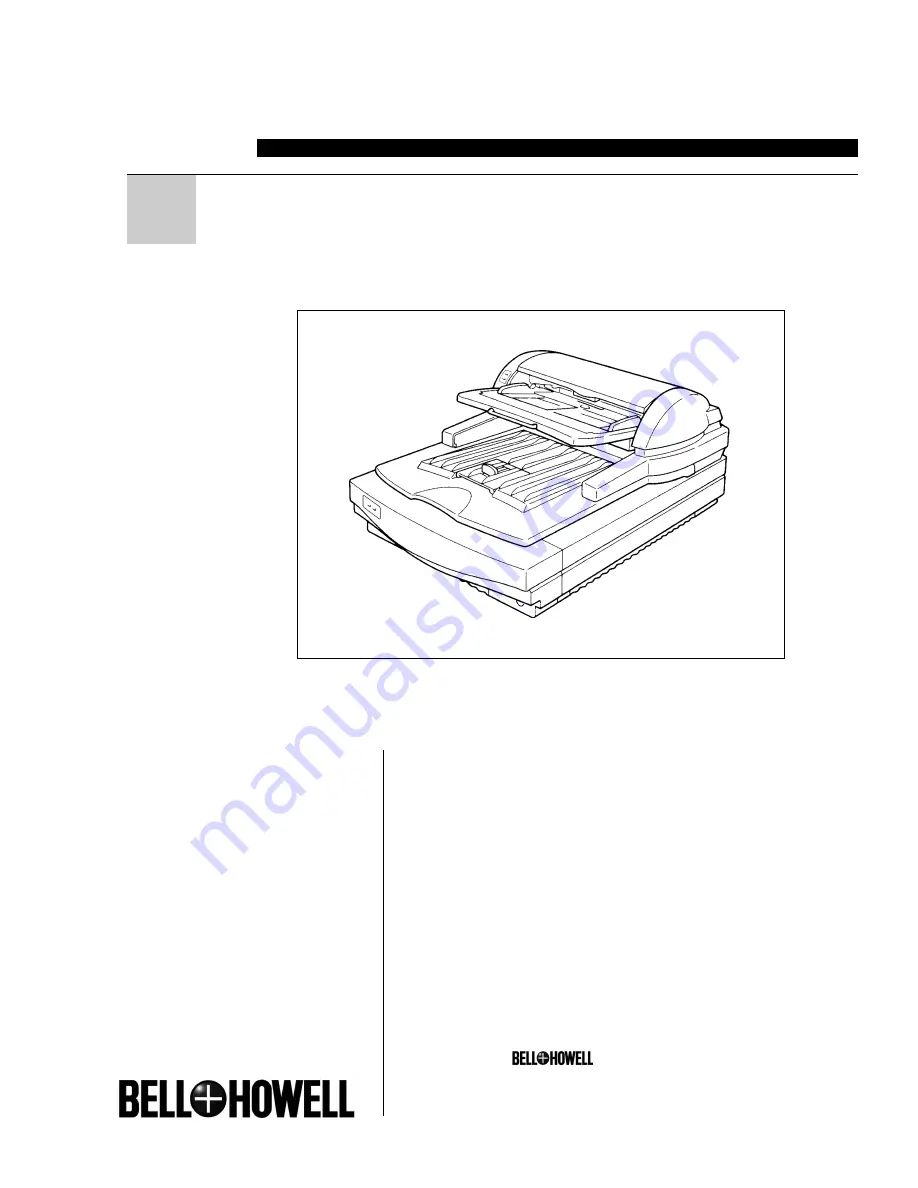
background image

S004011 Rev B 02-02

FB

SCANNER

2000

User Manual

Bell & Howell Scanners                        
3450 W. Pratt Ave., Lincolnwood, IL 60712
847.675.7600 (General)
800.SCAN.494 (Sales)
800.SCAN.495 (Technical Support)
Web Site: www.bhscanners.com

Bell & Howell and                         are trademarks of
Bell & Howell Company. All other trademarks are
the property of their respective owners.
© 2002 Bell & Howell

Summary of Contents for 2000 FB

Page 1: ...450 W Pratt Ave Lincolnwood IL 60712 847 675 7600 General 800 SCAN 494 Sales 800 SCAN 495 Technical Support Web Site www bhscanners com Bell Howell and are trademarks of Bell Howell Company All other trademarks are the property of their respective owners 2002 Bell Howell ...

Page 2: ...noring this warning could cause serious injury or even death CAUTION Ignoring this caution could cause injury or damage to property Examples of Indications Symbol R means a situation that requires you take care Do NOT carry out the operation represented by this symbol This example means Do not take apart Symbols mean you MUST perform this operation This example means You must remove the wall plug ...

Page 3: ...ock When the machine needs to be checked adjusted or repaired contact your service representatives Do not take apart or attempt any modifications to this machine There is a risk of fire electric shock explosion or loss of sight If the machine looks damaged or breaks down smoke is coming out there is a strange smell or anything looks unusual immediately turn off the power switch then unplug the pow...

Page 4: ...e unplug the power cord from the wall outlet to avoid fire or electric shock When the machine will not be used for a long time unplug the power cord When you pull out the plug from the socket grip the plug to avoid damaging the cord and causing fire or electric shock This machine has been tested for safety using this supplier s parts and consumables We recommend you only use these specified suppli...

Page 5: ... a 3 wire grounding type plug a plug having a third grouding pin This plug will only fit into a grounding type outlet This is a safety feature If you are unable to insert the plug into the outlet contact your electrician to replace your outlet Do not defeat the purpose of the grounding type plug by removing its grounding pin This does not apply in countries in which a 2 wire nongrounded type of pl...

Page 6: ...perating instructions since improper adjustment of other controls may result in damage and will often required extensive work by a qualified technician to restore the machine to normal operation E If the machine has been dropped or the cabinet has been damaged F If the machine exhibits a distinct change in performance indicating a need for service 14 Make sure that your wall outlet is close to the...

Page 7: ...jury when you misuse the machine without following the instructions under this symbol Be sure to read the instructions all of which are described in the Safety Information section The statements above are notes for your safety Important If this instruction is not followed paper might be misfeed originals might be dam aged or data might be lost Be sure to read this Note This symbol indicates precau...

Page 8: ...nned documents optional 1 Space saving design 2 Supports both TWAIN and ISIS 2 Guide to the Scanner 3 Understanding the Indicators 5 2 Setting up the Scanner Preparing for Installation 7 Checking the Scanner Location 7 Connecting to the Host Computer 10 What is SCSI 10 SCSI Connection Requirements for the Scanner 10 Setting the SCSI ID 11 Connecting the SCSI Cable No Connection to Other Port 11 Co...

Page 9: ...eral Scanning Method 25 Manual Scanning 26 5 Troubleshooting When Scanning Does Not Start 27 Error Indicators and Solutions 28 Procedures to Correct Errors in the ADF 29 When an Original is Jammed in the Auto Document Feeder ADF 29 When an Original was Not Output Properly from the Auto Document Feeder ADF 29 When There is a Problem with the Operation of the Document Table 29 When Characters Printe...

Page 10: ...40 Image Processing Unit Type A 40 Red Lamp Unit Type A 40 Endorser Unit Type A Printing Function 41 Specifications 42 Scanner Electrical and Hardware Specifications 42 DIP Switches 43 Functions 44 Preview 44 Scan 45 Scanning Composition 45 Binary Scanning Threshold 46 Halftone Scanning 47 Gray Scale Scanning 48 Area Extraction 49 Section Area Multi area Settings 50 Auto Photo Letter 51 Resolution...

Page 11: ...x ...

Page 12: ...sheet can be scanned simultaneously This capability eliminates the bother of having to flip document sheets over Direct operation using the buttons on the scanner Manual Scanning function If using a driver that supports the Manual Scanning function scanning can be initiated by pressing the Start button on the scanner This function is useful when scanning a document that needs to be set in place fo...

Page 13: ...ding elements such as a document tray This design allows the scanner to be set up next to a wall and permits office space to be used more effectively Supports both TWAIN and ISIS The scanner supports both the standard TWAIN and the newer ISIS driver allowing the scanner to function with a wide range of software ...

Page 14: ...n order to clean the En dorser printing function or replace the ink 5 Output Table After a document has been scanned by the Auto Document Feeder ADF it is output here 6 Stopper This stops documents that have been scanned and output by the Auto Docu ment Feeder ADF 7 Power Switch This switch is used to turn the scanner power on and off 8 Clear Modes Button This button is used to stop manual scan ni...

Page 15: ...switch is used to set the SCSI ID 6 SCSI Connector Connect the SCSI interface cable here 7 Interface for Reverse Side Scan ning This is an extension interface for reverse side scanning Duplex Model only 8 DIP Switches These switches are used to set the operat ing mode 9 Reset Switch This switch resets the scanner as if the power had been turned off and then back on again This switch is used to mak...

Page 16: ...n When the power has just been turned on or the Resetswitchhasbeenpressed Thiscombination is displayed only for a few seconds When there is no document in the Auto Docu ment Feeder and no document is being scanned When there is a document in theAuto Document Feeder but the document is not being scanned Whenscanneddataisbeingtransferred andthere is no document in theADF Whenscanneddataisbeingtransf...

Page 17: ...1 Introduction 6 ...

Page 18: ... Setup location Warning Make sure the wall outlet is near the machine and easily accessible so that in event of an emergency it can be unplugged easily Caution Keep the machine away from humidity and dust A fire or an electric shock might occur Do not place the machine on an unstable or tilted surface If it topples over it could cause injury Set up the scanner on a flat stable surface The surface ...

Page 19: ...nner in any of the types of locations listed below Doing so could cause the scanner to malfunction In a location exposed to direct sunlight In a location where the scanner will be subjected to blowing air or radiant heat such as near an air conditioner or heater In a location near other electronic devices such as a radio or television set In a location subject to extreme temperatures or humidity N...

Page 20: ...0 10 30 20 RH Recommended range Usable range TH2H061E C 50 F 80 80 6 F 80 77 F 70 77 F 30 89 6 F 54 89 6 F 15 50 F 15 59 F 30 59 F 70 80 60 40 20 50 80 90 60 70 RH Recommended range Usable range TH2H070E F Important Save the box and cushioning material in which the scanner was packed so that they can be used if it is necessary to transport the scanner in the future Preparing for Installation ...

Page 21: ...isy chain share the same SCSI ID misoperation and data loss may result Set a unique SCSI ID for this scanner that does not duplicate the SCSI ID of any other de vice SCSI Connection Require ments for the Scanner This scanner complies with the SCSI 2 standard SCSI 1 compliant peripheral devices can also be connected and used with this scanner The SCSI interface on the scanner has a 50 pin half pitc...

Page 22: ...hile the power is on it is necessary to initialize the scanner Refer to P 16 Initializ ing the Scanner Connecting the SCSI Cable No Connection to Other Port A Turn off the host computer and all peripheral devices that will be con nected through the SCSI interface B B B B B Use SCSI cables to connect the per sonal computer and the peripheral de vices in daisy chain fashion with this scanner at the ...

Page 23: ... connected through the SCSI interface B B B B B Use SCSI cables to connect the per sonal computer and the peripheral de vices in daisy chain fashion with this scanner in the middle of the daisy chain C C C C C Set DIP switch 3 to on This disables the scanner s internal termi nator For details on the functions of the DIP switches refer to P 43 DIP Switches ...

Page 24: ...n it pull it hard or bend it more than necessary These actions could cause an electric shock or fire Do not plug or unplug the power cord with your hands wet Otherwise an electric shock might occur Warning Be sure to ground the scanner Failure to ground the scanner could result in fire or electric shock If there is no ground connection available consult your dealer Caution When you pull out the pl...

Page 25: ... 14 B B B B B Push the power cable plug all of the way into the power connector on the scanner Note Use the power cable that was provided with this scanner C C C C C Plug the other end of the power cable into the power outlet ...

Page 26: ...isy chain away from the host computer and working towards the host computer Turn on the host computer last A A A A A Press the power switch so that it is in the Power On position as shown below Turning Off the Scanner Power A A A A A Press the power switch so that it is in the Power Off position as above Turning On Off the Scanner Power Turning On Off the Scanner Power ...

Page 27: ...order to put the new settings into effect To initialize the scanner either turn the power off and then back on again or else perform the procedure described below A A A A A Using an object with a thin tip such as a ballpoint pen press the reset switch located on the back of the scanner Doing so puts the scanner into the same state as if the power had been turned off and then back on again ...

Page 28: ...sult in a paper jam or in damage to the original Such originals should be placed on the contact glass An original that does not fall within the Recommended Sizes and Weights of Originals An original that includes staples paper clips glue or other adhesives An original that has holes or is torn An original that is warped creased or wrinkled An original that is pasted together An original that has s...

Page 29: ...ginal However the sizes of the following types of originals are difficult to detect properly even if using a scanner driver that supports automatic detection of the size of the original An original that has index tabs stick on notes or other protrusions An original that is highly transparent such as transparencies or tracing paper Documents on a dark background Documents with text illustrations or...

Page 30: ...s used overseas Irregular sizes A3 B 4 A4 A4 B 5 B 5 A5 A5 B 6 B 6 A6 11 x17 8 x14 8 x11 8 x5 8 x5 8 x5 Where original K K K L K L K L K L K DTL K LG K LT K LT L HLT K HLT K is placed Contact glass Auto Document Feeder ADF Original Sizes and Scanning Area Contact glass Auto Document Feeder ADF Originals ...

Page 31: ...A A A A Open the Auto Document Feeder ADF B B B B B With the side to be scanned facing down place the original on the contact glass and align it with the home position and scale 1 Home position 2 Scale Important Do not press down on the contact glass Strong localized pressure on the contact glass could cause it to break C C C C C Gently close the Auto Document Feeder ADF ...

Page 32: ...z i S f o r e b m u N n a c t a h t s t e e h s t e s e b m m 5 1 6 0 m g 5 0 1 2 b l 4 2 5 A 4 A T L H T L 0 1 1 3 A T L D 0 8 m g 4 6 2 b l 0 2 3 A 5 A 4 A T L D T L H T L 0 5 1 Limitation When the original has a dark background the scanner may not be able to recognize that a document has been placed in the ADF If this happens place the document on the contact glass instead A A A A A Align the o...

Page 33: ...ide it back into the table and adjust the position Refer to the diagram below Important When the stopper is extended do not grasp the stopper when opening or closing the Auto Document Feeder ADF B B B B B Put the originals in order If they are to be scanned in page sequence put them in order as illustrated below Simplex scanning Duplex scanning ...

Page 34: ...an the sheets and then line up their edges D D D D D With the first page facing up on top place the originals in the Auto Document Feeder ADF and adjust the positions of the guides so that they touch the edges of the original 1 Guides ...

Page 35: ...3 Setting Originals 24 ...

Page 36: ...e that is TWAIN or ISIS compatible The method of operation depends on the software For details refer to the manual that was supplied with your software Limitation When using double sided scanning if the leading edge of the reverse side of the document is dark the scanned image may appear whitish ...

Page 37: ...munications between the scanner and the personal computer are no longer needed in cases where it is necessary to set the original in the scanner one sheet at a time for example A A A A A Set the manual scanning function through the scanner driver B B B B B Set the original in the scanner C C C C C Press the Start button To end manual scanning press the Clear Modes button TH2H220E 1 Clear Modes But...

Page 38: ...on whether this scanner is the last device in the SCSI daisy chain Refer to P 11 Connecting the SCSI Cable and set the DIP switches properly Are the SCSI cables connected securey If any cables are disconnected connect them Are the indicators on or flashing The nature of an error can be determined according to the pattern in which the four indicators are on or flashing Refer to P 28 Error Indicator...

Page 39: ...t Feeder ADF There is a problem with the operation of the document table The Endorser printing function may have malfunctioned System error On Flashing Off Action Close theAuto Document Feeder ADF or the ADF cover Refer to P 29 Procedures to Correct Errors in the ADF and remove the jammed paper Refer to P 29 Procedures to Correct Errors in the ADF and remove the paper that was not output Refer to ...

Page 40: ... a original is jammed in the feed rollers grasp the leading edge of the original and gently pull it out in the direction of the ADF cover When an Original was Not Out putProperlyfromtheAutoDocu ment Feeder ADF A A A A A Open the ADF cover B B B B B Pull out the original WhenThereisaProblemwith the Operation of the Docu mentTable A A A A A Remove the original from the Auto Document Feeder ADF B B B...

Page 41: ... printing becomes too light A A A A A Turn off scanner power and unplug the power cable from the power outlet B B B B B Flip open the Endorser cover located towards the rear of the output table and pull the cover out C C C C C Grasp the green portion of the Endorser and turn it in the direction indicated by the arrow until it clicks When Characters Printed by the Endorser are Too Light or the Orig...

Page 42: ...diagram D D D D D Raise the rear portion of the Endorser and then pull the Endorser out Important Do not pull on the Endorser s cord E E E E E Place the Endorser down with the printing section facing up Important Do not touch the printing section of the Endorser Doing so may get your fin gers dirty and could damage the printing section When Characters Printed by the Endorser are Too Light or the O...

Page 43: ... If paper scraps and dust accumulate in the vicinity of the printing section of the En dorser printing quality will be adversely affected If the printing section becomes dirty gently wipe the portion shown in white in the illustration below with a dry soft cloth Important Do not wipe any portion other than that which is shown in white above In addi tion do not touch the printing section Doing so m...

Page 44: ...ock Periodic cleaning is required in order to maintain this scanner in good condition First wipe away any dirt with a dry soft cloth If the dirt cannot be removed with a dry cloth moisten a soft cloth with water wring it out thoroughly and then wipe away the dirt If water is not sufficient to remove the dirt wipe off the dirt with a mild detergent solution then wipe the detergent away with water a...

Page 45: ...outlet B B B B B Wipe these components with a soft dry cloth Cleaning the Feed Roller and Drum A A A A A Turn off scanner power and unplug the power cable from the power outlet B B B B B Open the ADF cover and then while turning the feed roller and drum by hand wipe them with a damp cloth that has been thoroughly wrung out To turn the drum turn the blue knob 1 White Sheet 2 Platen 3 Slit Glass 4 C...

Page 46: ...feed roller after scanning an original that was written in pencil or with some other material that is not solidly fixed on the paper If you do not clean the feed roller it may dirty the next original that is scanned Maintenance ...

Page 47: ...A A A Turn off scanner power and unplug the power cable from the power outlet B B B B B Open the Auto Document Feeder ADF and pull off the white sheet which is held in place by cellophane tape C C C C C While turning the blue knob on the drum in the direction indicated by the arrow wipe the white roller with a damp cloth that has been thoroughly wrung out 1 White roller 2 Drum D D D D D Place the ...

Page 48: ...ion Note Make sure that the white sheet does not lie on the scales 1 Home position 2 Scales F F F F F Gently close the Auto Document Feeder ADF and press it down on it firmly G G G G G Open the Auto Document Feeder ADF again and rub a cloth against the entire surface of the white sheet Maintenance ...

Page 49: ...rd from the wall outlet to avoid fire or electric shock When the machine will not be used for a long time unplug the power cord Caution When you pull out the plug from the socket grip the plug to avoid damaging the cord and causing fire or electric shock The minimum time for which will be kept inventories of replacement parts needed for maintenance services is seven years from the date that a mode...

Page 50: ...o yourself carry the scanner to its new location Important When carrying the scanner try to keep it as level as possible Shipping the Scanner When shipping the scanner pack it in its original shipping carton Important Disconnect all cables Because the scanner is a precision instrument pack it carefully so that it will not be damaged while in transit Disposing of the Scanner When you wish to dispos...

Page 51: ...d scans each in a suitable scan mode Limitation During double sided scanning this function is valid only for the front side of the original Document Size Detection This function automatically detects the width of an original and sends the information to the host computer Section Area This function selects an area within an original and sets scanning conditions for that area Limitation During doubl...

Page 52: ... Endorser UnitTypeA printing function can print a symbol or number on originals that have been scanned by the Auto Document Feeder ADF The Endorser Unit Type A printing function settings are made through the scanner driver For details on how to set the Endorser Unit TypeA refer to the manual and help provided for the scanner driver that you will be using Options ...

Page 53: ...5ppm A4K 200dpi binary 57ppm LTK 200dpi binary Duplex Model 81ppm A4K 200dpi binary 84ppm LTK 200dpi binary ppm pages per minute Warm up time Max 15 seconds Interface SCSI 2 50 pin half pitch pin type x 2 Power consumption Simplex Model 50W maximum when in standby options installed 90W maximum when operating options installed Duplex Model 80W maximum when in standby options installed 120W maximum ...

Page 54: ...I ID with the rotary switch If the daisy chain is too long or if a nonstandard SCSI cable is used misoperation may occur during synchronous transfer In this case set DIP switch 2 to ON SCSI synchronous transfer disabled If this scanner is connected in the middle of a daisy chain set DIP switch 3 to ON internal SCSI terminator off Leave these set to OFF do not change OFF Internal SCSI terminator on...

Page 55: ...erates according to the scanner driver settings but some scanner driv ers do not support all of the scanner functions In such a case the unsupported func tions are not available for use In addition the names used in this manual for certain functions may differ from the names used by the scanner driver For details refer to the scanner driver manual Preview This function scans the entire scanning ar...

Page 56: ...nning halftone scanning and multi value scanning Binary scanning This mode scans the original in black and white This mode is used to scan originals that consist only of text line drawings and other elements that lack intermediate colors Halftone scanning This mode scans the original in pseudo halftones created by dots This mode is used to output an original that contains intermediate colors such ...

Page 57: ...two colors such as text or line drawings The threshold value should be set according to the intensity of the original For example setting a high threshold value when scanning faint text will produce text that is muchclearer Conversely setting a low threshold value when scanning an original that is on a colored background such as text on colored paper will eliminate the background color from the sc...

Page 58: ... only produce monochrome output such as a laser printer Because halftone scanning expresses pseudo halftones it does not require as much memory making it effective for filing a large volume of images There are eleven types of halftones ten dot shading patterns and one error diffusion pattern for selection It is also possible to scan and download your own dot shading patterns The names in parenthes...

Page 59: ...on an output device that can express intermediate tones for a single pixel such as a display or a Dye Sublimation printer Although a higher number of bits produces higher image quality it is important to remember that the processing time will be longer For example when an area is scanned using the 8 bit multi scan mode it requires eight times as much memory as when scanning the same area through b...

Page 60: ...scan just the photograph portion of the original shown below specify the area where the photograph is located The rectangular area is specified by specifying the coordinates of the upper left corner of the rectangle and the vertical and horizontal lengths k Functions Scanned result Specified area Original Scanned image ...

Page 61: ... one scan Limitation During double sided scanning this function is valid only for the front side of the original Note Note that scanning might not be performed in the specified manner if any of the four rectangular areas overlap In this case either decrease the number of rectangles or else reduce them in size This function is valid only when the optional Image Processing Unit Type A is installed k...

Page 62: ...r to automatically scan text in binary scanning mode and photos in halftone scanning mode This function allows you to scan an original that contains both text and photos just once while automatically scanning each type of area in the appropriate scanning mode without having to make special settings for each Note This function is valid only when the optional Image Processing Unit Type A is installe...

Page 63: ...quality will suffer if the resolution is less than that of the output device and it is meaningless to set a resolution that is higher than the resolution that the output device is capable of However if the output image is to be enlarged or reduced compared to the original change the resolution by the same ratio Limitation When this function is used during duplex scanning the maximum image data siz...

Page 64: ... portion will also appear in the scanned image Conversely if the bright portions of an original become solid white in the scanned image lowering the brightness value will bring out the gradations in the bright portion in the scanned image Contrast The contrast can be adjusted to 255 levels If a high contrast value is set the resulting image will have high contrast and will be sharply defined If a ...

Page 65: ...e original that is to be scanned and the output device Normal Emphasizes the contrast slightly resulting in a somewhat sharp scanned image Sharp Emphasizes the contrast resulting in a sharp scanned image Soft Decreases the contrast resulting in a soft scanned image Linear Outputs the image as scanned User defined Downloads a user defined gamma curve for gamma correction Normal Sharp Soft Linear ...

Page 66: ...ng Smoothing This filter is used to smooth out small bumps within an image Note This function is valid only when the optional Image Processing Unit Type A is installed Parameter Download This function allows a user to download user created gamma curves and halftone patterns to the scanner The details of how to download the data depends on the software being used When filter is not used When filter...

Page 67: ... the leading edge 5mm 0 2 of the original the size of the original might not be detected properly If the sheets of the original are not set in position properly the size of the original might not be detected properly Line up the edges of the sheets of the original and position the guides on both sides so that they are touching the edges of the original and will ensure that the original feeds strai...

Page 68: ...e Background is disabled The dynamic range is set so that a white original D value 0 07 reaches maximum output When Erase Background is enabled During scanning the portion of the original that is closest to white is deemed to be white and the dynamic range is set so that the portion in question reaches maximum output ...

Page 69: ... 27 43 Document in Place 5 Document Size Detection 40 56 Document Table 3 29 Drum 34 Duplex Model 1 42 Dynamic Threshold 40 E Endorser 1 28 30 31 32 41 42 Endorser Cover 3 30 Erase Background 57 Error 5 F Feed roller 29 35 G Gamma Correction 54 Gray Scale Scanning 45 48 H Halftone Scanning 45 47 Home Position 20 37 I Image Processing 40 Indicators 5 27 28 Initializing the Scanner 16 ink ribbon 30 ...

Page 70: ...ion 52 Rotary Switch 4 11 S Scale 20 SCAM 10 43 Scanner Indicators 3 Scanning Composition 45 SCSI 10 SCSI Board 10 SCSI Cables 10 11 27 39 SCSI Connector 4 SCSI ID 10 11 27 SectionArea Multi area Settings 50 Simplex Model 42 Slit Glass 34 Start Button 3 26 Stopper 3 21 22 T Terminator 10 11 43 Threshold 46 TWAIN 2 25 W White Roller 36 White Sheet 4 34 36 Index ...

Page 71: ...6 Appendices 60 ...

Reviews: