background image

Installation MACH102

Release 07 12/2020

Technical support

https://hirschmann-support.belden.com

User Manual

Installation
Industrial ETHERNET Workgroup Switch
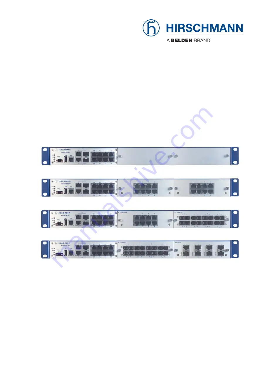
MACH102 Family

MACH102-8TP-F

MACH102-24TP-F

MACH102-8TP + M1-8TP-RJ45 + M1-8MM-SXC

MACH102-8TP + M1-8SM-SXC + M1-8SFP

Summary of Contents for Hirschmann MACH102 Series

Page 1: ...12 2020 Technical support https hirschmann support belden com User Manual Installation Industrial ETHERNET Workgroup Switch MACH102 Family MACH102 8TP F MACH102 24TP F MACH102 8TP M1 8TP RJ45 M1 8MM SXC MACH102 8TP M1 8SM SXC M1 8SFP ...

Page 2: ...e performance features described here are binding only if they have been expressly agreed when the contract was made This document was produced by Hirschmann Automation and Control GmbH according to the best of the company s knowledge Hirschmann reserves the right to change the contents of this document without prior notice Hirschmann can give no guarantee in respect of the correctness or accuracy...

Page 3: ...rface external management 26 2 Assembly and start up 27 2 1 Installing the device 27 2 1 1 Checking the package contents 27 2 1 2 Installing media modules 27 2 1 3 Installing an SFP transceiver optional 28 2 1 4 Signal contact FAULT 29 2 1 5 Installing the device and grounding 30 2 1 6 Supply voltage 34 2 1 7 Operating the device 37 2 1 8 Connecting data cables 37 2 1 9 Support of PoE 40 2 2 Displ...

Page 4: ...dia modules 50 7 3 Signal contact 50 7 4 Interfaces 50 7 5 Climatic conditions during operation 51 7 6 Climatic conditions during storage 51 7 7 Dimension drawings 52 7 8 EMC and immunity 53 7 9 Network range 54 7 9 1 10 100 1000 Mbit s twisted pair port 54 7 9 2 Fast Ethernet SFP transceiver 54 7 9 3 Gigabit Ethernet SFP transceiver 55 7 10 Power consumption power output temperature range and ord...

Page 5: ...injury or death If this symbol is displayed in addition to a safety instruction of the type Danger or Warning it means that there is a danger of electric shock and failure to observe the instructions will inevitably result in injury This symbol indicates the danger of hot surfaces on the device In connection with safety instructions non observance of the instructions will inevitably result in inju...

Page 6: ...6 Installation MACH102 Release 07 12 2020 NOTICE NOTE provides information about procedures that do not involve the risk of injury ...

Page 7: ...l to work on the device Qualified personnel have the following characteristics Qualified personnel are properly trained Training as well as practical knowledge and experience make up their qualifications This is the prerequisite for grounding and labeling circuits devices and systems in accordance with current standards in safety technology Qualified personnel are aware of the dangers that exist i...

Page 8: ...ctrical wires Before connecting the electrical wires always verify that the requirements listed are complied with Requirements for connecting the signal contact The following requirements apply without restrictions The electrical wires are voltage free The cables used are permitted for the temperature range of the application case The device is grounded via the voltage supply socket see figure 19 ...

Page 9: ...tified So in the case of an emergency it is clear which disconnecting device belongs to which power supply cable Install a fuse in the outer conductor of the power supply Connect the neutral conductor to the ground potential If the neutral conductor is not connected to the ground potential also install an external fuse in the neutral conductor Regarding the properties of this fuse See Power supply...

Page 10: ...pment is available for the safe handling of electrostatically endangered assemblies Further information about electrostatic sensitive modules can be found in DIN EN 61340 5 1 2007 08 and DIN EN 61340 5 2 2007 08 Device casing Only technicians authorized by the manufacturer are permitted to open the casing The device is grounded via the voltage supply socket Never insert sharp objects small screwdr...

Page 11: ...ed in a control cabinet or other enclosure with fire protection properties The enclosure can be made of metal or plastic with fire protection properties of at least V 1 according to IEC 60695 11 10 Bottom openings must not exceed 2 mm in diameter Strain relief Note If the strain relief is insufficient there is a risk of torsion contact problems and creeping interruptions Relieve the connection poi...

Page 12: ...ly cables and data cables do not run parallel over longer distances To reduce inductive coupling verify that the power supply cables and data cables cross at a 90 angle Use shielded data cables for gigabit transmission via copper cables for example SF UTP cables according to ISO IEC 11801 Exclusively use shielded data cables to meet EMC requirements according to EN 50121 4 and marine applications ...

Page 13: ...ates relating to the making available on the market of electrical equipment designed for use within certain voltage limits In accordance with the above named EU directive s the EU conformity declaration will be at the disposal of the relevant authorities at the following address Hirschmann Automation and Control GmbH Stuttgarter Str 45 51 72654 Neckartenzlingen Germany www doc hirschmann com certi...

Page 14: ...nd to comply with the limits for a Class A digital device pursuant to part 15 of the FCC Rules These limits are designed to provide reasonable protection against harmful interference when the equipment is operated in a commercial environment This equipment generates uses and can radiate radio frequency energy and if not installed and used in accordance with the instruction manual may cause harmful...

Page 15: ...iption safety instructions a description of the display and the other information that you need to install the device Documentation mentioned in the User Manual Installation that is not supplied with your device as a printout can be found as PDF files for downloading on the Internet at https www doc hirschmann com ...

Page 16: ...16 Installation MACH102 Release 07 12 2020 Key The symbols used in this manual have the following meanings Listing Work step Subheading ...

Page 17: ... relevant industry standards provide very high operational reliability even under extreme conditions and also long term reliability and flexibility The Hirschmann network components help you ensure continuous communication across all levels of the company The MACH102 devices provide you with a range of switch variants You can set up your switch to meet your individual requirements with regard to t...

Page 18: ...and also long term reliability and flexibility The device allows you to set up switched Industrial Ethernet networks according to standard IEEE 802 3 The Gigabit Ethernet Combo ports alternatively connectable via F O or TX of the basic devices are suitable for connecting end devices or network segments according to the standards IEEE 802 3 100 1000BASE FX SFP slot and IEEE 802 3 1000BASE TX 100BAS...

Page 19: ...g properties MACH102 8TP MACH102 8TP R 2 Gigabit ETHERNET Combo ports 8 Fast ETHERNET ports You have the option of choosing the media for an additional 8 or 16 ports via the media modules MACH102 8TP R Power supply is designed redundantly Figure 2 Overview over interfaces display and operating elements of the MACH102 8TP and MACH102 8TP R 1 MACH102 device 2 LED display elements 3 Signal contact 4 ...

Page 20: ...n 1 7 See the following table column 2 GigabitETHERNET GE ports 1 2 Combo ports Fast ETHERNET FE ports 1 8 Fast ETHERNET FE ports 9 24 2 slots for optional media modules 100 1000 Mbit s F O SFP slots Alternatively 10 100 1000 Mbit s Twisted Pair RJ45 ports 8 Twisted pair TX RJ45 10 100 Mbit s 8 Twisted pair TX RJ45 10 100 Mbit s or 8 Twisted pair TX PoE RJ45 10 100 Mbit s or 8 Multimode FX DSC 100...

Page 21: ...column 2 1 2 2 MACH102 media modules Figure 5 Media module for MACH102 Example M1 8MM SC The MACH102 media modules form the interface from the device to the LAN Gigabit ETHERNET GE ports 1 1 and 1 2 Combo ports Fast ETHERNET FE ports 2 1 2 8 3 1 3 8 4 1 4 8 100 1000 Mbit s F O SFP slots Alternatively 10 100 1000 Mbit s Twisted Pair RJ45 ports 24 Twisted pair TX RJ45 10 100 Mbit s LS DA USB V 24 MA...

Page 22: ...rnet ports each and only differ in the type of port The different interfaces of the MACH102 media modules provide you with the following interface specific functions Specific functions TP TX port Link Control Auto Polarity Exchange Autonegotiation Autocrossing device may be connected with a crossed over or an un crossed cable Specific functions of fiber optic interface Link Down monitoring MACH102...

Page 23: ... ports This port is an RJ45 socket The 10 100 Mbit s PoE port allows you to connect network components as a PoE voltage sink according to the standard IEEE 802 3 10BASE T 100BASE TX and IEEE 802 3af Autonegotiation Autopolarity Autocrossing if autonegotiation is activated The devices support the connection and a remote power supply of e g IP phones Voice over IP webcams sensors print servers and W...

Page 24: ...optical ports are configured in 100 Mbit s Fullduplex FDX and support FEFI They have a DSC design Figure 8 Media module M1 8MM SC Media module M1 8SM SC The M1 8SM SC media module has 8 FX ports for connecting terminal devices or network segments in compliance with the IEEE 802 3u 100BASE FX Singlemode standard The optical ports are configured in 100 Mbit s Fullduplex FDX and support FEFI They hav...

Page 25: ...rature range and order numbers SFP stands for Small Form factor Pluggable and is also often referred to as mini GBIC GigaBit Interface Converter The SFP modules are plugged into the SFP slots of the MACH102 basic device to obtain an F O port The MACH102 has 2 TP interfaces and 2 slots for inserting SFP modules 100 1000 Mbit s By inserting the SFP module you deactivate the corresponding TP interfac...

Page 26: ...e Interface CLI and to the system monitor The socket casing is electrically connected to the front panel of the device The V 24 interface is not electrically isolated from the supply voltage Figure 11 Pin assignment of the V24 interface Note You find the order number for the terminal cable which can be ordered separately here See Accessories on page 58 VT 100 terminal settings Speed 9600 Baud Data...

Page 27: ...package contents Check whether the package includes all items named in the section Scope of delivery on page 58 Check the individual parts for transport damage 2 1 2 Installing media modules On delivery the device is ready for operation The modules are can be used in the following basic devices MACH102 8TP MACH102 8TP R Note the chapters ESD Guidelines on page 10 and General safety instructions Th...

Page 28: ...en the 2 screws at the corners of the media module Fit the media modules in sequence from left to right 2 1 3 Installing an SFP transceiver optional Prerequisites Exclusively use Hirschmann SFP transceivers See Accessories on page 58 Figure 13 Installing SFP transceivers Installation sequence Proceed as follows Take the SFP transceiver out of the transport packaging 1 Remove the protection cap fro...

Page 29: ...ontact closed circuit reports through a break in contact The detected failure of at least one of the two supply voltages supply voltage 1 or 2 is below the threshold value A detected continuous malfunction in the device The detected defective link status of at least one port The link state can be masked for each port in the graphic user interface In delivery state link monitoring is inactive Excee...

Page 30: ...al data Keep the ventilation slits free to ensure good air circulation Make sure there is at least 3 94 in 10 cm of space in front of the ventilation slits of the casing The assembly location can be accessed for maintenance and repair work The LED display elements are clearly visible Twisted pair cables are at a sufficient distance from potential sources of electrical interference such as power su...

Page 31: ... the back and the data cables to be fitted at the front Assemble the sliding or mounting rails in the 19 switch cabinet as specified by the manufacturer Figure 16 Assembly in a switch cabinet with sliding mounting rails 1 MACH102 device 2 sliding mounting rail 3 19 switch cabinet On delivery two brackets are attached to the sides of the device see figure below Figure 17 Mounting the MACH102 in the...

Page 32: ...he switch cabinet using 2 holding brackets on the back of the device You obtain the additional brackets as accessories See Accessories on page 58 CAUTION OVERHEATING OF THE DEVICE When installing the device make sure any ventilation slots remain free Maintain a clearance of at least 3 94 in 10 cm Failure to follow these instructions can result in injury or equipment damage ...

Page 33: ...7 12 Fasten the device by screwing the brackets to the wall Note The shielding ground of the connectable industrial twisted pair lines is connected to the front panel as a conductor Grounding The device is grounded via the voltage supply socket see figure 19 and see figure 20 CAUTION OVERHEATING OF THE DEVICE When installing the device make sure any ventilation slots remain free Maintain a clearan...

Page 34: ...er supply 100 V AC 240 V AC MACH102 8TP R MACH102 8TP FR MACH102 24TP FR The supply voltage can be connected redundantly Both inputs are uncoupled The load is not distributed With redundant supply the standard power supply supplies the device on its own The redundant power supply becomes active automatically if the standard power supply fails Normally the redundant power supply runs in stand by mo...

Page 35: ...agement Connecting the PoE supply voltage to the M1 8TP RJ45 PoE media module optional WARNING ELECTRIC SHOCK Supply only 48 V DC PoE SELV or ES1 or 54 V DC PoE SELV or ES1 to the M1 8TP RJ45 PoE media module For the PoE power supply to the M1 8TP RJ45 PoE media module use a fuse of 5 A with slow blow characteristic Install this device only in a switch cabinet or in an operating site with restrict...

Page 36: ...it you use to provide the PoE voltage fulfills the following basic prerequisites Insulation requirements according to IEEE 802 3af insulation resistance 48 V output to rest of the world 2250 V DC for 1 min Output power 250 W and sufficient to provide the power for the connected PDs Current limitation 5 A or fuse 5 A slow blow WARNING FIRE HAZARD Disconnect the PoE voltage supply before removing th...

Page 37: ...or to the protective conductor terminal Connect the PoE voltage to the 3 pin terminal block 2 1 7 Operating the device By connecting the voltage supply via the voltage supply socket s you start the operation of the device 2 1 8 Connecting data cables Note the following general recommendations for data cable connections in environments with high electrical interference levels Keep the length of the...

Page 38: ...l duplex mode 10 Mbit s half duplex mode 10 Mbit s full duplex mode Delivery state Autonegotiation activated The port casing is electrically connected to the front panel 10 100 Mbit s PoE port This port is an RJ45 socket The 10 100 Mbit s PoE port allows you to connect network components as a PoE voltage sink according to the standard IEEE 802 3 10BASE T 100BASE TX and IEEE 802 3af This port suppo...

Page 39: ...lex 100 Mbit s full duplex 10 Mbit s half duplex 10 Mbit s full duplex Delivery state Autonegotiation The socket casings are electrically connected to the front panel The pin assignment corresponds to MDI X Figure 22 Pin assignment of the 1000 Mbit s twisted pair port 100 Mbit s F O port This port is a DSC socket or an SFP slot The 100 Mbit s F O port allows you to connect network components accor...

Page 40: ...PoE is exclusively available with PoE capable media modules The Workgroup Switch basic device has no PoE capable ports Exclusively media module M1 8TP RJ45 PoE supports Power over Ethernet PoE Prerequisites for the support of PoE At least 1 media module with PoE functionality M1 8TP RJ45 PoE is mounted in the basic device The 10 100 Mbit s PoE port allows you to connect network components as a PoE...

Page 41: ...ue RM Ring Manager green yellow LED Glowing green RM function active redundant port not active Glowing yellow RM function active redundant port active Not glowing RM function not active Flashing green Incorrect configuration of the HIPER Ring e g the ring is not connected to the ring port Sb StandBy Stand by mode green LED Glowing green Stand by mode enabled Not glowing No Stand by mode FAULT Sign...

Page 42: ...ght LED informs you about PoE voltage supply on a port as shown in table 9 LS Data Link Status 1 green yellow LED or 1 green and 1 yellow LED Not glowing No valid connection Glowing green Valid connection Flashing green 1 time a period Port is switched to stand by Flashing green 3 time a period Port is disabled Flashing yellow Data reception Table 8 Data Link Status PoE voltage supply Not glowing ...

Page 43: ...t the Hirschmann product pages HiView http www hirschmann com en QR INET HiView Industrial HiVision http www hirschmann com en QR INET Industrial HiVision Further information on the basic settings of the device can be found in the Basic Configuration user manual on the CD DVD Default settings IP address The device looks for the IP address using DHCPa Password for management Login user password pub...

Page 44: ...ou to type in a new password Type in your new password To help increase security choose a password that contains at least 8 characters which includes upper case characters lower case characters numerical digits and special characters When you log on to the device with the Command Line Interface then the device prompts you to confirm your new password Log on to the device again with your new passwo...

Page 45: ... locking mechanism 2 Close the SFP transceiver with the protection cap 3 4 2 Removing a media module To remove the media module first remove the two screws at the corners of the media module Pull the media module out of the slot Fasten the protective cover to the slot using the two screws WARNING FIRE HAZARD Disconnect the PoE voltage supply before removing the M1 8TP RJ45 PoE media module Non adh...

Page 46: ...witch cabinet or the wall remove the screws from the brackets on the device Figure 25 Dismounting WARNING ELECTRIC SHOCK Disconnect the grounding only after disconnecting all other cables Failure to follow these instructions can result in death serious injury or equipment damage LS DA USB V 24 MACH 1000 2 1 LS DA 3 4 9 10 P StandBy RM FAULT R1 R2 5 6 7 8 13 14 11 12 17 18 15 16 21 22 19 20 25 26 2...

Page 47: ...m from the device It depends on the installation conditions of the device for example the distance from other devices or other objects and the output of neighboring devices The temperature displayed in the CLI and the GUI is the internal temperature of the device It is higher than the ambient air temperature The maximum internal temperature of the device named in the technical data is a guideline ...

Page 48: ... are triggered only in the case of a detected error in the device In case of damage or malfunction of the device turn off the supply voltage and return the device to the plant for inspection Hirschmann is continually working on improving and developing their software Check regularly whether there is an updated version of the software that provides you with additional benefits You find information ...

Page 49: ...tion Class 1 in compliance with IEC 60825 1 Degree of protection IP20 Dimensions See Dimension drawings on page 52 Weight M1 8TP RJ45 0 46 lb 210 g M1 8MM SC 0 46 lb 210 g M1 8SM SC 0 4 lb 180 g M1 8SFP 4 59 oz 130 g M1 8TP RJ45 PoE 0 57 lb 260 g Max PoE power Per media module 124 W Pollution degree 2 Protection classes Laser protection Class 1 in compliance with IEC 60825 1 Rated voltage range 10...

Page 50: ...N 62368 1 Connection type Version 2 pin terminal block with screw lock Tightening torque 3 lb in 0 34 Nm max conductor diameter AWG16 1 3 mm Table 10 Signal contact Basic devices MACH102 8TP MACH102 8TP R MACH102 8TP F MACH102 8TP FR MACH102 24TP F MACH102 24TP FR 1 V 24 connection external management 2 terminal block 2 pin signal contact max 1 A 24 V 1 USB interface ACA22 MACH102 8TP MACH102 8TP ...

Page 51: ...t s Singlemode Duplex SC connector M1 8SFP 8 100 Mbit s SFP slot Climatic conditions during operation Ambient air temperaturea a Temperature of the ambient air at a distance of 2 in 5 cm from the device Standard up to 6562 ft ASL 2000 m ASL 32 F 122 F 0 C 50 C Maximum inner temperature of device guideline 203 F 95 C Humidity 10 95 non condensing Air pressure min 600 hPa 13123 ft 4000 m max 1060 hP...

Page 52: ...stallation MACH102 Release 07 12 2020 7 7 Dimension drawings 482 6 19 319 12 56 308 12 13 31 75 1 25 44 1 73 465 9 18 34 2 1 2 3 2 5 2 7 2 2 2 4 2 6 2 8 1 3 5 7 2 4 6 8 1 3 5 7 2 4 6 8 1 1 1 2 V 24 USB mm in ...

Page 53: ...gnetic field 80 MHz 3000 MHz max 20 V m EN 61000 4 4 Fast transients burst Power line Data line 2 kV 4 kV EN 61000 4 5 Voltage surges Power line line line Power line line earth Data line 1 kV 2 kV 4 kV EN 61000 4 6 Line conducted interference voltages 150 kHz 80 MHz 10 V EN 61000 4 9 Pulse magnetic fields 300 A m EMC interference emission EN 55032 Class A Yes FCC 47 CFR Part 15 Class A Yes ...

Page 54: ... lengthb b Including 3 dB system reserve when compliance with the fiber data is observed Fiber attenuation BLP dispersion M FAST SFP MM LC MM 1310 nm 50 125 µm 0 dB 8 dB 0 mi 3 11 mi 0 km 5 km 1 0 dB km 800 MHz km M FAST SFP MM LC MM 1310 nm 62 5 125 µm 0 dB 11 dB 0 mi 2 49 mi 0 km 4 km 1 0 dB km 500 MHz km M FAST SFP SM LC SM 1310 nm 9 125 µm 0 dB 13 dB 0 mi 15 53 mi 0 km 25 km 0 4 dB km 3 5 ps n...

Page 55: ...km 1 0 dB km 500 MHz km M SFP LX LC MM 1310 nmc 50 125 µm 0 dB 10 5 dB 0 mi 0 34 mi 0 km 0 55 km 1 0 dB km 800 MHz km M SFP LX LC MM 1310 nmd 62 5 125 µm 0 dB 10 5 dB 0 mi 0 34 mi 0 km 0 55 km 1 0 dB km 500 MHz km M SFP LX LC SM 1310 nm 9 125 µm 0 dB 10 5 dB 0 mi 12 43 mi 0 km 20 km e 0 4 dB km 3 5 ps nm km M SFP LX LC SM 1310 nm 9 125 µm 5 dB 20 dB 8 70 mi 26 10 mi 14 km 42 km 0 4 dB km 3 5 ps nm...

Page 56: ...ance with the fiber data is observed c With F O adapter compliant with IEEE 802 3 2002 Clause 38 single mode fiber offset launch mode conditioning patch cord d With F O adapter compliant with IEEE 802 3 2002 Clause 38 single mode fiber offset launch mode conditioning patch cord e Including 2 5 dB system reserve when compliance with the fiber data is observed Product code Modea Wave length Fiber Sy...

Page 57: ...02 family with 2 Gigabit Ethernet combo port 24 Fast Ethernet TX and redundant power supply Media modules M1 8TP RJ45 8 Fast Ethernet TX RJ45 M1 8TP RJ45 PoE 8 Fast Ethernet TX RJ45 PoE M1 8MM SC 8 Fast Ethernet Multimode DSC connector M1 8SM SC 8 Fast Ethernet Singlemode DSC connector M1 8SFP 8 Fast Ethernet SFP slot MACH102 Family Device module power consumpti on power output Operating temperatu...

Page 58: ...0 C 943 970 201 M1 8SFP incl SFP modules 11 W 37 Btu IT h 32 F 122 F 0 C 50 C 943 970 301 Device Numb er Scope of delivery MACH102 8TP MACH102 8TP R MACH102 8TP F MACH102 8TP FR MACH102 24TP F MACH102 24TP FR 1 MACH102 device 1 Terminal block for signal contact 2 Mounting brackets with fastening screws pre mounted 1 Casing feet stick on 1 Non heating appliance cable Euro model 1 CD DVD with manual...

Page 59: ...modules M SFP MX LC 942 035 001 M SFP SX LC 943 014 001 M SFP SX LC EEC 943 896 001 M SFP LX LC 943 015 001 M SFP LX LC EEC 943 897 001 M SFP LX LC 942 023 001 M SFP LX LC EEC 942 024 001 M SFP LH LC 943 042 001 M SFP LH LC EEC 943 898 001 M SFP LH LC 943 049 001 Name EN 61000 6 2 Electromagnetic compatibility EMC Part 6 2 Generic standards Immunity for industrial environments EN 55032 Electromagn...

Page 60: ...C 2132 DHCP Options RFC 826 ARP RFC 2236 IGMPv2 RFC 951 BOOTP RFC 2239 MAU MIB RFC 1112 IGMPv1 RFC 3411 SNMP Framework RFC 1157 SNMPv3 RFC 3412 SNMP MDP RFC 1155 SMIv1 RFC 3413 SNMP Applications RFC 1213 MIB2 RFC 3414 SNMP USM RFC 1493 Dot1d RFC 3415 SNMP VACM RFC 1542 BOOTP Extensions RFC 2613 SMON RFC 1757 RMON RFC 2674 Dot1p Q Table 18 List of RFCs IEEE 802 1 D Switching GARP GMRP Spanning Tree...

Page 61: ... Competence Center is ahead of its competitors on three counts with its complete range of innovative services Consulting incorporates comprehensive technical advice from system evaluation through network planning to project planning Training offers you an introduction to the basics product briefing and user training with certification You find the training courses on technology and products curren...

Page 62: ......

Reviews: