Beko METPOINT BDL compact, Installation And Operating Manual
The Beko METPOINT BDL compact is a cutting-edge device that offers unmatched precision in air measurement. Ensure seamless operation with the comprehensive "Instructions For Installation And Operation Manual." Download the manual for free from manualshive.com and take full advantage of this remarkable product.
Share
Download


Reviews:
No comments
Related manuals for METPOINT BDL compact

N4250
Brand: Haldex Pages: 3
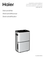
HEN70ETFP
Brand: Haier Pages: 36

CXW-219-D69
Brand: Haier Pages: 13
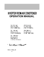
H2SM-21HX03
Brand: Haier Pages: 27

HRFZ-250D AA
Brand: Haier Pages: 104

Suki 12
Brand: Suki Pages: 6

5000
Brand: fish mate Pages: 3

DLR-BT001 Series
Brand: Datalogic Pages: 49

Microcor MWT-3905-MDL
Brand: ROHRBACK COSASCO SYSTEMS Pages: 4

STOELTING AutoFill
Brand: Vollrath Pages: 3

MP-2
Brand: Ruelco Pages: 3

VG06011
Brand: VIGO Pages: 50

DURASTALL 30
Brand: Mustee Pages: 6

Flex
Brand: SUPERNOVA Pages: 12

Link PR
Brand: Danfoss Pages: 60

OBID i-scan ISC.LR200-A/B
Brand: Feig Electronic Pages: 27

CLEANSTATION CSIIP
Brand: Stratasys Pages: 11

MPR5000
Brand: DataCard Pages: 1


