background image

EN

Instruction & Technical Manual

46 - 110

BEKO TECHNOLOGIES CORP. 900 Great SW Parkway, Atlanta, Georgia 30336, 

USA

+1 (800) 235-6797 Phone +1 (404) 629-6666 Fax  [email protected] www.bekousa.com
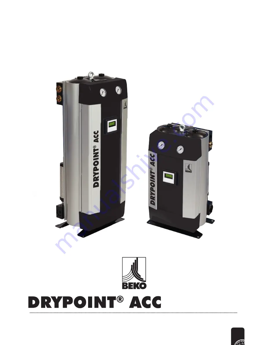
Summary of Contents for DRYPOINT ACC 110

Page 1: ...EN Instruction Technical Manual 46 1 10 BEKO TECHNOLOGIES CORP 900 Great SW Parkway Atlanta Georgia 30336 USA 1 800 235 6797 Phone 1 404 629 6666 Fax beko bekousa com www bekousa com ...

Page 2: ...t personnel Please complete the following information at the time of installation found on the rating label on the upper right hand side of dryer Model Number Serial Number Inlet Pressure Filtration present with Dryer Inlet Flow of Dryer Supply Voltage When contacting the manufacturer regarding this product please have the above stated information at hand to speed up your query ...

Page 3: ...ions 10 Dimensional Specifications 11 Sizing 12 4 Mechanical Installation 13 Orientation 15 Configuration of the inlet outlet ports 16 Connecting the pre filter to the dryer 17 Connecting the post filter to the dryer 17 Configuring the purge orifice 18 5 Electrical Installation 20 Controller power supply options 20 Controller specifications 21 How to wire a DIN connector 22 Alarm connection detail...

Page 4: ...egy 31 Using a manual switch for purge control 31 Using a standard pressure switch for purge control 31 Using an electronic pressure switch for purge control 33 Using a hygrometer and process controller for purge control 34 Making connections between a switching device and dryer EM contact 34 8 Maintenance 36 9 Spares Information 37 Service kits 37 41 Accessory kits 42 10 Component Parts 43 11 Tro...

Page 5: ...ical disconnection plus isolation from the compressed air supply and full depressurisation Only trained and competent persons familiar with the electrical requirements of the unit as laid out in this manual and electrical safety rules and regulations should be allowed to carry out work on the electrical components and power supply to the unit When carrying out any work on the unit use only correct...

Page 6: ... the responsibility for their own Health and Safety and the Health and Safety of others around them If you feel there is a significant risk you must take steps to either remove the risk altogether or reduce the risk prior to carrying out the activity If you need further support or guidance with this please consult your line manager or the HR Department There are safe systems of work and correct pr...

Page 7: ... silencer which is fitted to an exhaust valve The tower is then repressurized with the control system assuring each tower is at full operational pressure prior to changeover This ensures a reliable and efficient operation The air stream is switched and the cycle repeats on a continuous basis General Description Section 2 General Description This manual is valid for the following dryer models ACC 4...

Page 8: ...e equipped with eyebolts to facilitate removing the dryer from its crate Simplex dryers include one eyebolt Note All dryers include spare orifice components to allow the dryer to be modified from the factory 100 psig 7 barg pressure setting to any pressure within the specified operating range The internal purge valves within models 45 SCFM 55 SCFM can be modified to suit all pressure settings whil...

Page 9: ...anel 2 Digital Display Controller 3 Top trim cover 4 Extrusion cover 5 Top extrusion tower plug 6 Tower Spacer 7 Desiccant cartridge 8 Extrusion tower 9 Top manifold assembly 10 Water Separator recommended 11 Downpipe 12 Exhaust silencer 13 Bottom manifold assembly 14 Dryer stand 15 Bottom extrusion tower plug 16 Tower circlip 17 Bottom trim cover 18 Pre filter general purpose 1 0 µ 19 Pre filter ...

Page 10: ... 100 psig 7 barg Inlet temperature 95 F 35 C Relative humidity of air at inlet 95 Pressure dewpoint standard version 40 F 40 C Specified Limitation for Operation Measurement Performance Maximum inlet air pressure 188 5 psig 13 barg Minimum inlet air pressure 58 psig 4 barg Maximum ambient air temperature 122 F 50 C Minimum ambient air temperature 41 F 5 C Pressure dewpoint 4 F to 100 F 20 C to 74 ...

Page 11: ...ex ACC 75 1 75 128 35 6 905 14 0 380 12 2 310 3 0 76 1 96 50 33 4 850 137 62 2 simplex ACC 90 1 90 153 40 55 1030 14 0 380 12 2 310 3 0 76 1 96 50 39 3 1000 155 70 2 simplex 1 ACC 110 1 110 187 49 6 1260 14 0 380 12 2 310 3 0 76 1 96 50 27 5 700 187 85 4 simplex 1 Stated flows are for an inlet pressure of 100 psig 7 barg with reference to 4 F 14 50 psig abs 0 relative water vapor pressure For flow...

Page 12: ...3 122 Celcius C 20 25 30 35 40 45 50 Correction factor 1 3 1 2 1 1 1 0 0 75 0 65 0 45 Pressure dewpoint DCF Farenheit F 4 22 40 94 100 Celcius C 20 30 40 70 74 Correction factor 1 23 1 2 1 0 0 8 0 77 Dryer correction factors Section 3 Technical Data 45 SCFM 110 SCFM To correctly select the dryer model suitable for your application the following information is required Minimum Inlet Pressure Maximu...

Page 13: ...Critical 0 01 µ 0 01 µ reverse flow Non return Check Valve Figure 4 2 Level ground Mechanical Installation Section 4 Mechanical Installation To prevent back flow into the dryer a non return valve should be placed in line downstream of the dryer This is essential when more than one dryer is used in a single application ...

Page 14: ...igure 4 4 Hard piped installation Figure 4 5 Exposure to heat Figure 4 3 Location Max 122O F 50O C Max 122O F 50O C Max 122O F 50O C Max 122O F 50O C Max 122O F 50O C Max 122O F 50O C Max 122O F 50O C Max 122O F 50O C Max 122O F 50O C Max 122O F 50O C Max 122O F 50O C Max 122O F 50O C ...

Page 15: ...on Figure 4 7 The range of dryers is designed to operate in both vertical and horizontal orientation 16 Heatless Desiccant Dryers Instruction Manual Section 4 Mechanical Installation Figure 4 6 Drainage all tubing should be secured up to the point of drain to prevent whipping during discharge Orientation Figure 4 7 The range of dryers is designed to operate in both vertical and horizontal orientat...

Page 16: ... blanked off with provided pressure plugs Figure 4 8 Inlet outlet ports A C B D Either of the two outlet ports can be used Please ensure that the outlet flow does not exceed specification Please adhere to regional regulations It is strongly advised to install a non return check valve to the outlet port of the dryer Only use one inlet port at any one time Ensure original seals are in place Check dr...

Page 17: ...loose for field installation utilizing a pipe nipple and or pipe adapter user supplied Pipe away condensate with tubing from drain outlet Ensure condensate is drained into an oil Water Separator Fit any additional filtration and or ancillary equipment Pre filter is typically supplied with a float drain installed in the bowl drain port This can be replaced with the optional BEKOMAT drain It is reco...

Page 18: ...ct orifice disc 01 02 has been supplied with the dryer The discs have the number 01 02 stamped out at the top Every dryer is shipped with a purge orifice set up for 100 psig 7 barg operation The dryer will also include the necessary purge valve components to configure the dryer to operate at any pressure from 58 psig 4 barg to 189 psig 13 barg For example A 110 SCFM dryer will be supplied with a s...

Page 19: ...e 4 11 Purge valve assembly Purge Valve Assembly Reference figure 4 11 and the Purge Plug Identification Table on Page 18 Once the correct orifice disc 01 or 02 has been selected per the instructions on Page 18 the purge valve may be assembled The index letters located on the purge valve body correspond with the selected orifice sizes per the Table on Page 18 Place the appropriate orifice disc ont...

Page 20: ...tions Models 45 SCFM 110 SCFM The dryer is designed to operate on either AC or DC supply voltage Dryers are supplied with AC power supply and attached 115VAC USA power cord The power supply may be removed to allow 24VDC to be supplied directly to the controller Reference Figure 5 1 for details on controller power supply connections ...

Page 21: ...Controller 24VDC Power Rating 16W Max Protection class IP65 Transient over voltage IEC 60664 Class II Pollution degree 2 IEC 60664 A circuit breaker or switch must be installed near the dryer This should be easy to reach and shall be certified according to EN60947 1 and EN60947 3 The switch or circuit breaker shall be marked as the disconnecting device for the dryer and needs to be marked with on ...

Page 22: ... gland should point C arefully pull the cable back through the case until the insert snaps back into place Take care to workthe wires around the retaining screw hole as they can become fairly easily pinched P lug the DIN connector back onto the appropriate electrical 5 1 and 5 2 Take care to make sure that sealing gasket is in place The male ground pin is slightly wider than pins 1 2 Take care to ...

Page 23: ...rnally powered alarm indication device to the corresponding terminals of the controller s alarm output For details regarding wiring of female DIN connector refer to How to wire a DIN connector on page 22 Alarm Connection Details Hirschmann GDS 207 industrial std DIN connector or equivalent Alarm Contact Rating Digital Display Controller 0 5 AMPS 24VDC Fig 5 4 Alarm contact connections DMC Controll...

Page 24: ...on stream removing water vapor the other is being carefully depressurized in preparation for regeneration The desiccant bed is regenerated by expanding a small amount of dry process air or purge air through the saturated desiccant Purge air passes to atmosphere through the silencer which is fitted to an exhaust valve The chamber is then repressurized with the control system assuring each chamber i...

Page 25: ...s from the dryer Switch on electric power the panel will display the operational features The dryer will enter standard cycle mode Open valve B slowly Shut down Procedure Close valve B Close valve A Leave dryer running for 15 minutes to fully de pressurize Switch off all electrical power to the dryer On initial commissioning run the dryer for a minimum of 6 hours to ensure dewpoint is adequate bef...

Page 26: ...passes through both towers A IN OUT Purge Control Non Return Valve Purge Control Non Return Valve A A ON OFF ON Wet Purge Dry OFF SV 1 Left Solenoid Control Valve LEGEND SV 2 Right Solenoid Control Valve Seconds 0 120 154 274 308 Alternate Outlet Position Alternate Inlet Position 1 0µ reverse flow After Filter Standard Running Mode Hours Run 456 Service History 0 3 2 1 3 1 2 SV1 Left Solenoid Cont...

Page 27: ...gh the left purge orifice and down through the left tower to regenerate the off stream left desiccant bed Purge Control Non Return Valve Purge Control Non Return Valve IN OUT A A A ON OFF ON Wet Purge Dry OFF SV 2 Right Solenoid Control Valve LEGEND SV 1 Left Solenoid Control Valve Seconds 0 120 154 274 308 Alternate Outlet Position Alternate Inlet Position 1 0µ reverse flow After Filter Standard ...

Page 28: ...e Control Non Return Valve Purge Control Non Return Valve IN OUT A A A ON OFF ON Wet Purge Dry OFF SV 2 Right Solenoid Control Valve LEGEND SV 1 Left Solenoid Control Valve Seconds 0 120 154 274 308 Alternate Outlet Position Alternate Inlet Position 1 0µ reverse flow After Filter Standard Running Mode Hours Run 456 Service History 0 3 1 2 3 1 2 Silencer Silencer Controller Left Tower Pressure Gaug...

Page 29: ...e right purge orifice and down through the right tower to regenerate the off stream right desiccant bed Purge Control Non Return Valve Purge Control Non Return Valve IN OUT A A A ON OFF ON Wet Purge Dry OFF SV 2 Right Solenoid Control Valve LEGEND SV 1 Left Solenoid Control Valve Seconds 0 120 154 274 308 2 Seconds Alternate Outlet Position Alternate Inlet Position 1 0µ reverse flow After Filter S...

Page 30: ...urge Control Non Return Valve Purge Control Non Return Valve IN OUT A A A ON OFF ON Wet Purge Dry OFF SV 2 Right Solenoid Control Valve LEGEND SV 1 Left Solenoid Control Valve Seconds 0 120 154 274 308 Alternate Outlet Position Alternate Inlet Position 1 0µ reverse flow After Filter Standard Running Mode Hours Run 456 Service History 0 3 1 2 3 1 2 Silencer Silencer Controller Left Tower Pressure G...

Page 31: ...note that specific details differ between device manufacturers so in all cases the manufacturer s specifications should be adhered to Fig 7 1 Manual switch purge control 35 Fig 7 1 M anu al switch p urge c ontro l LED Controller Overview Regenerative dryers must expel a portion of the process air in order to free themselves of accumulated moisture During periods of low air demand however this air ...

Page 32: ...actuates at 95 psig in example The point at which the switch deactuates may be adjusted to suit the system If it is determined that the dewpoint drops to an unacceptable level the deactuation point must be increased Please note that with most standard pressure switches the dead band is fixed such that the activation and deactuation points move together It is extremely important to understand that ...

Page 33: ...stomised operation Typically thedead band can be reduced or eliminated so that an immediate reaction to It is extremely important to understand that the purge may only beshut during periods oflow or no demand This feature if used otherwise can result in permanent damage to the desiccant beds resulting in loss of drying capacity and possibly mechanical failure The cartridges must not be allowed to ...

Page 34: ...break Conductors can be swapped without having to run new cable A conductor gauge of no greater than 18 awg is recommended to fit comfortably into the DIN connector insert An outside diameter of no greater than 1 4 6mm Larger diameters do not fit well into the cable gland of the EM DIN connectors An insulation type compatible with the environment that it will be run in Figure 7 5 Process controlle...

Page 35: ...d should point Carefully pull the cable back through the shell until the insert snaps back into place Take care to work the wires around the retaining screw hole as they can become fairly easily pinched Plug the DIN connector back onto the dryer s EM connection The male ground pin is slightly wider than pins 1 2 Take care to ensure that the female connector is oriented correctly Figure 7 7 Connect...

Page 36: ...s Applicable Service Kits Pre Filter Element Every 1 year or 6000 hours Exhaust silencer Every 1 year or 6000 hours Desiccant cartridges Every 2 years or 12000 hours Main shuttle Every 4 years or 24000 hours Exhaust shuttle Every 4 years or 24000 hours Solenoid valves Every 4 years or 24000 hours Purge orifice Every 4 years or 24000 hours Important information Ensure shutdown and start up procedur...

Page 37: ...5 12 000 hours or 2 years Maintenance Kit A Dryer Model Kit Part Number with float drain Kit Part Number with BEKOMAT Description Change Out Period ACC 46 4054029 Consult factory 12 000 Hour Maintenance Kit A Kit includes all components in the 1 year kit plus desiccant cartridges sealing o rings with washers and service manual 12 000 Hours or 2 Years ACC 56 4054030 Consult factory 12 000 Hours or ...

Page 38: ...tridge Silencer Service Kit for use where 100 F 74 C dewpoint is required Dryer Model Kit Part Number Description Change Out Period DPACC 46 4054034 12 000 Hour High Performance Desiccant Cartridge and Silencer Kit Kit includes High Performance desiccant cartridges and associated seals and silencer service kit reference figures 10 2 10 3 and 10 4 supplied with cartridge removal tool 12 000 Hours o...

Page 39: ...e Out Period ACC 46 4054039 Consult factory 24 000 Maintenance Kit B Kit includes all componenets in the 1 year and 2 year kits plus a complete valve service kit and service manual 24 000 Hours or 4 Years ACC 56 4054040 Consult factory 24 000 Hours or 4 Years ACC 75 4054041 Consult factory 24 000 Hours or 4 Years ACC 90 4054042 Consult factory 24 000 Hours or 4 Years ACC 110 4054043 Consult factor...

Page 40: ... Kit Part Number Description Change Out Period DPACC 46 4054044 24 000 Hour High Performance Service Kit Kit includes High Performance Cartridge Set silencer service kit solenoid kit shuttle service kit and purge valve kit supplied with cartridge removal tool 24 000 Hours or 4 Years DPACC 56 4054045 24 000 Hours or 4 Years DPACC 75 4054046 24 000 Hours or 4 Years DPACC 90 4054047 24 000 Hours or 4...

Page 41: ...ete kit for dryers operating between 58 psig 188 5 psig 4 barg 13 barg and appropriate purge orifice discs fully assembled reference figure 10 5 Dryer Model Kit Part Number Description ACC 46 4055293 45 SCFM 55 SCFM Purge valve kit ACC 56 ACC 75 4055309 75 SCFM 110 SCFM Purge valve kit ACC 90 ACC 110 Shuttle Service Kit Kit includes 1 control shuttle 2 exhaust shuttles and associated seals referen...

Page 42: ...r Supply Lead 24VDC controller only Din Plug Kit Kit includes 1 3 pole ground industrial standard DIN connector Dryer Model Kit Part Number Description ACC 46 to ACC 110 Consult factory Female DIN plug kit Although the power supply is supplied separately as an accessory and meets the required CE and UL approval it is the responsibilty of a competent person installing the equipment that all local i...

Page 43: ...st Assembly Included in Service Accessory Kit Valve Service 24 000 hr Shuttle 6 000 12 000 18 000 and 24 000 hr Service 24 000 hr 2 6 10 5 4 3 2 11 8 13 12 9 1 7 1 8 7 4 3 10 6 9 5 2 14 44 Component parts Fig 10 1 To p m anif old assembl y Section 10 Component Parts Fig 10 2 B ottom manifold assembl y 1 1 2 2 2 2 1 8 2 2 2 1 1 1 1 2 2 2 8 2 2 2 4 2 Itm Qty Description 2 3 4 5 6 7 8 9 10 Inlet outl...

Page 44: ...2 4 2 2 2 2 1 4 4 1 Itm Qty Description 2 3 4 5 6 7 8 9 10 Tower extrusion Extrusion tower plug Desiccant cartridge Quantity varies per dryer model Cartridge spacer Support circlip Service cap outer O ring Floor mounting bracket Service cap inner O ring Trim caps Controller reset magnet Included in Service Accessory Kit Desiccant Cartridge 12 000 and 24 000 hour Master Seal 7 8 2 9 10 4 3 1 5 6 ...

Page 45: ...ve stem 1 Hole Valve stem 2 Hole Valve stem 3 Hole Included in Service Accessory Kit Purge Valve Body 1 Hole Purge Valve Body 2 Hole Purge Valve Body 3 Hole Purge Orifice Disc 2 1 1 2 3 4 5 13 14 6 7 8 12 9 11 10 Fig 10 4 Controller Assembly 45 SCFM 110 SCFM Section 10 Component Parts Fig 10 5 Purge valve kits 0 10 5 Controller assembl ies 10 6 Purge valve assembly 2 1 1 2 Itm Qty Description Sole...

Page 46: ...nt life exceeded Replace desiccant cartridges Desiccant contaminated Check inlet filter and drains replace cartridges EM is active when air is flowing through dryer Check EM wiring Power to dryer off while air is flowing through dryer Ensure that power is on whenever air is flowing through dryer Incorrect dryer operation won t switch towers Jammed shuttle valves Clean or replace shuttles Faulted e...

Page 47: ...er specifications given in Section 5 Faulty external indication device Repair or replace device Faulty controller Replace controller Troubleshooting Energy Management Problem Possible Cause Action Dryer does not enter Energy Management when switching device is activated and or Dryer does not enter Energy Management when EM contacts are opened Shorted or incorrect device wiring Remove external wiri...

Page 48: ...ryer functioning in standard running mode service overdue Line message 1 STANDARD RUNNING MODE Line message 2 Line message 3 SERVICE OVERDUE Line message 4 SERVICE HISTORY XX Service overdue 12000 hours continuous operation Energy management mode active Line message 1 ENERGY MANAGEMENT MODE Line message 2 Line message 3 HOURS RUN XXXXX Line message 4 SERVICE HISTORY XX Energy management mode activ...

Page 49: ...rs The manufacturer desiccant dryer range is designed for warrantied and intended for use in fixed industrial compressed air applications only Use on non fixed installations such as marine e g offshore shipboard transportable e g portable air treatment units non fixed e g rolling stock railway etc are not strictly prohibited however use in such applications is not recommended nor endorsed as addit...

Page 50: ...50 Heatless Desiccant Dryers Instruction Manual Notes ...

Page 51: ...51 Heatless Desiccant Dryers Instruction Manual Notes ...

Page 52: ...52 Heatless Desiccant Dryers Instruction Manual Notes ...

Page 53: ...53 Heatless Desiccant Dryers Instruction Manual Notes ...

Page 54: ...S CORP 900 Great SW Parkway Atlanta Georgia 30336 USA 1 800 235 6797 Phone 1 404 629 6666 Fax beko bekousa com www bekousa com BEKO reserves the right to make changes and improvements to the product and or this manual without prior notice ...

Reviews: