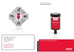
Beko BEKOMAT 14i, Manual
The Beko BEKOMAT 14i is a reliable and efficient compressed air condensate drain for your industrial applications. With its user-friendly interface and seamless operation, this product ensures optimal performance. Download the free user manual from manualshive.com to maximize your experience with this exceptional condensate drain.
Share
Download


Reviews:
No comments
Related manuals for BEKOMAT 14i

K-5339T-KT100
Brand: Kohler Pages: 10

DRINKWELL HY-DRATE PFD17-12899
Brand: Petsafe Pages: 1

Claris
Brand: Jura Pages: 11

Hydro-Guard HG-4
Brand: Mueller Pages: 8

FAST DISK
Brand: Laica Pages: 2

3000-6000-12000
Brand: SuperFish Pages: 12

EuroPEK Filter
Brand: Wavin-Labko Pages: 11
FLEX PLUS Series
Brand: Perma Pages: 22

SLZN 64N
Brand: Sanela Pages: 3

WQS44RJ1
Brand: LG Pages: 32
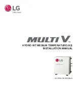
MULTI V HYDRO KIT ARNH423K2A4
Brand: LG Pages: 111
Premium 5231JA2002A-S
Brand: LG Pages: 2

WW130NP
Brand: LG Pages: 36

WS410GN
Brand: LG Pages: 20

WW162EP
Brand: LG Pages: 36

WW152NP
Brand: LG Pages: 36

WW174NPC
Brand: LG Pages: 36

9700464
Brand: Antunes Filtration Technologies Pages: 20


