

Interface Introduction
JetNet 7612G/5612G supports 8 ports Gigabit Ethernet RJ-45, and 4 ports
swappable 100/1000 Ethernet SFP socket for fiber connection.
Mounting the DIN Rail
The DIN Rail clip on the rear of JetNet 7612G/5612G, and supports 35mm
DIN rail.
Power Details
You can configure JetNet 7612G/5612G Series via the RS-232 console with
the attached console cable. Or you can remotely manage the switch via
network. You can choose Telnet/SSH, Web/HTTPS management.
Preparation for console management
Attach the RS-232 DB9 connector to your
PC’s
COM port. Connect the RJ-45
connector to the console port of the JetNet Switch.
1. Go to Start
►
Program
►
Accessories
►
Communication
►
Hyper
Terminal
2. Give a name to the new console connection.
3. Choose the COM name and select the correct serial settings. The serial port
settings are as below: Baud Rate:115200/Parity: None/Data Bit: 8/Stop Bit: 1
4. After connected, you will see the Switch login request. Type the username
and password and then you can login. The default username is
“admin”,
password is
“admin”
.
5. Follow the manual to configure the software features.
Preparation for Web management
1. Launch the web browser on the PC.
2. Type http://JetNet Managed Switch_IP_Address (The default IP address is
192.168.10.1.), then press Enter.
3. The login screen will appear next. Type in the user name and password and
click
“OK”
button. The default user name and password is admin/admin.
4. At the left column of the web management interface are the software
features, where ring column will list the available settings.
JetNet 7612G/7612GP/5612G/5612GP
Quick Installation Guide V1.0
Overview
Installation
Device Management
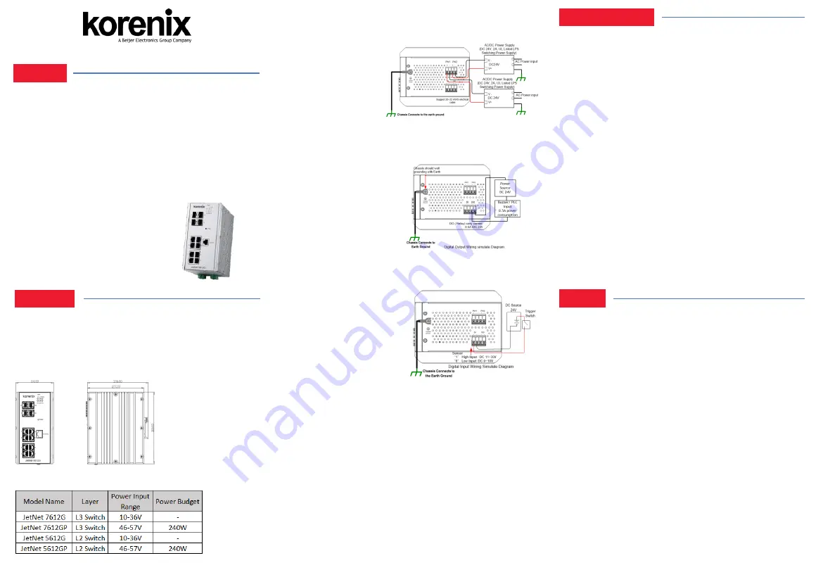
Wiring the Power Inputs & Earth Grounding
1. Insert the positive and negative wires into the V+ and V- contact on the
terminal block connector.
2. Connect the Chassis
Grounding to Earth Ground
system to obtain electromagnetic
immunity to resist lighting,
electro static discharge and
electric fast transient.
3. Tighten the wire-clamp screws to prevent the power wires from being
loosened.
Notes:
The recommended working voltage is listed in
“Power Details”
Wiring the Relay Output
The relay output contacts are
in the bottom side. The relay
output (DO) is controlled by
the pre-defined operating
rules. To activate relay output
function, please refer to the
User’s
Manual for more relay
output management information.
Notes:
The relay contact only supports 0.5 A current, DC 24V. It is not
recommended to apply voltage and current higher than the specifications.
The JetNet 7612G/5612G Series is an pure Gigabit Managed Switch
with 8 ports Gigabit Ethernet plus , and 4 100/1000 SFP for optical
fiber connection It adopts high efficiency Ethernet MAC controller
with 24Gbps Switch fabric bandwidth, 9K jumbo frame forwarding and
powerful capability. The robust system design makes the JetNet
7612G/5612G Series survive under harsh outdoor environment with
extreme electric magnetic interference and the variation of environment
temperature. The hardware switching with high performance, low
latency and security. It provides your network infrastructure with great
performance and safety with network access control, and handle burst
packet with smart buffer management for IP surveillance in real
infrastructure
.
Package Check List
JetNet 7612G/7612GP/5612G/5612GP
DIN Mounting kit
DB-9 to RJ-45 (RS-232) Console Cable
Quick Installation Guide
Wiring the Digital Input
The Digital Input (DI) contacts are
in the bottom. It accepts one external
DC type signal input and can be
configured to send alert message
through Ethernet when the signal
is changed. The signal may trigger
and generated by external power
switch, like as door open trigger switch for control cabinet.
Note: the DI accepts DC type signal and supports isolated input circuit with
Digital High Level input DC 11V~30V and Digital Low Level input DC
0V~10V. Do not apply voltage higher than the specification; it may cause
internal circuit damage or a wrong action of DI.
Connect to Network
1.
Connect the Ethernet Port: Connect the Ethernet port of JetNet
7612G/5612G Series with the other Ethernet device by Cat-5/Cat-6
UTP or STP cable, and then the LNK/ACT LED will turn on and start
flashing to indicate the communication is occurred between 2 device.
2.
Connect the SFP Port: Plug in SFP fiber transceiver. We recommend
using Korenix certificated SFP mini GBIC transceiver. Cross-connect
the transmit channel at each end to the receive channel at the opposite
end.
5 Years Warranty
Each of
Korenix’s
product is designed, produced, and tested with high
industrial standard. Korenix warrants that the product(s) shall be free from
defects in materials and workmanship for a period of five (5) years from the
date of delivery provided that the product was properly installed and used.
This warranty is voided if defects, malfunctions or failures of the warranted
product are caused by damage resulting from force measure (such as floods,
fire, etc.), other external forces such as power disturbances, over spec power
input, or incorrect cabling; or the warranted product is misused, abused, or
operated, altered and repaired in an unauthorized or improper way.
Attention! To avoid system damage caused by sparks, please DO NOT
plug in power connector when power is on.
The product is in compliance with Directive 2002/95/EC and 2011/65/EU of
the European Parliament and of the Council of 27 January 2003 on the
restriction of the use of certain hazardous substances in electrical and
electronics equipment (RoHS Directives & RoHS 2.0)
Korenix Customer Service
KorenixCARE is Korenix
Technology’s
global service center, where our
professional staffs are ready to answer your questions at any time.
Email address of Korenix Global Service Center : [email protected]
Support


