Beast-Tek Instruments Transmuter V1.5, Build Manual
The Beast-Tek Instruments Transmuter V1.5 Build Manual is your essential guide to assembling and using this groundbreaking equipment. Available for free download from our website, this comprehensive manual provides step-by-step instructions and detailed diagrams, ensuring a seamless and hassle-free setup process. Visit manualshive.com to access the manual and unlock the full potential of your Transmuter V1.5.
Share
Download


Reviews:
No comments
Related manuals for Transmuter V1.5

DJ-80
Brand: MC Crypt Pages: 81

Lost Highway Phaser
Brand: Fender Pages: 8

DM 1835X
Brand: Numark Pages: 20

ND-I NOVA DELAY
Brand: TC Electronic Pages: 20

PEPBOOST
Brand: Palmer Pages: 2

OnAir 2000M2
Brand: Studer Pages: 449

M-8
Brand: PROEL Pages: 30

HQ POWER VDSM02
Brand: Velleman Pages: 7

PROMIX100
Brand: Velleman Pages: 12

MXR Phase 45
Brand: Dunlop Pages: 2

103177
Brand: HEADRUSH Pages: 24

Alliance A1
Brand: Dedoes Pages: 25
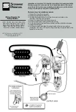
APH-1
Brand: Duncan Pages: 2

Warbler
Brand: Expert Sleepers Pages: 14

CLMPARFOOT
Brand: Cameo Pages: 95

CR-1604
Brand: Mackie Pages: 9

B-Type
Brand: Cadac Pages: 142

D8B
Brand: Mackie Pages: 3


