Beast-Tek Instruments Mutagen V1.5, Build Manual
The Beast-Tek Instruments Mutagen V1.5 Build Manual is an essential resource for anyone looking to assemble their own Mutagen V1.5 unit. This comprehensive manual provides step-by-step instructions and detailed illustrations, ensuring a smooth and hassle-free assembly process. Download your free copy from our website today and bring your Mutagen V1.5 to life.
Share
Download


Reviews:
No comments
Related manuals for Mutagen V1.5

MACCHERONI BROS
Brand: Tefi Vintage Lab Pages: 2

intellimix
Brand: Yellowtec Pages: 32

MPX-22
Brand: IMG STAGE LINE Pages: 26

DM 1885X
Brand: Numark Pages: 16

PEMP-8
Brand: Pyle Pro Pages: 33

PMX-120
Brand: Gemini Pages: 9
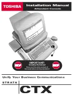
Strata CTX
Brand: Toshiba Pages: 24

LICSTAR-IV SE
Brand: Toshiba Pages: 262
Strata CTX
Brand: Toshiba Pages: 533

Vi Series
Brand: SoundCraft Pages: 12

200BVE
Brand: SoundCraft Pages: 41

Columbus
Brand: Diezel Pages: 8

SELECTOR
Brand: Whirlwind Pages: 2

U.S Audio MPM-1
Brand: Whirlwind Pages: 6

Mix 6
Brand: Whirlwind Pages: 6

FUZZFACE FFM2 MINI
Brand: Dunlop Pages: 2

SM 82
Brand: Rane Pages: 6

eSAM603
Brand: Ecler Pages: 36


