f
f
O
o
N
n
o
i
t
p
i
r
c
s
e
D
o
N
y
e
K
1
s
n
o
i
t
c
u
r
t
s
n
I
A
B
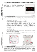
Programmable Room Thermostat (Transmitter)
1
1
t
i
n
U
r
e
v
i
e
c
e
R
C
2
)
A
A
/
6
R
L
V
5
.
1
(
y
r
e
t
t
a
B
D
E
Infill Panel
1
A
B
D
E
C
7658807-01 (4/16)
KIT CONTENTS IDENTIFICATION
en
United Kingdom
Please keep these instructions in a safe place.
If you move house, please hand them over to the next occupier.
Installation and Operating Instructions
Single Channel Wireless
24 Hour Programmable Room Thermostat
Part No. 7658781
Baxi Customer Support
0344 871 1545
baxi.co.uk
Baxi
Brooks House,
Coventry Road,
Warwick, CV34 4LL
e&oe
All descriptions and illustrations provided in this document have been
carefully prepared but we reserve the right to make changes and
improvements in our products which may affect the accuracy of the
information contained in this leaflet. All goods are sold subject to our
standard Conditions of Sale which are available on request.
Regulation EU811/2013, supplementing Ecodesign and
Energy Labelling Directives 2010/30EU
Part
Number
This Thermostatic
Control Device is rated
Correction Factor
(Contribution to system
energy efficiency)
7658781
Class ‘I’
1 %
ErP Information
Comp N
o 7212346 - Iss 03 (07/15)
en
United Kingdom
Please keep these instructions in a safe place.
If you move house, please hand them over to the next occupier.
Installation and Operating Instructions
Single Channel Wireless
24 Hour Programmable Room Thermostat
Part No. 7212343
Regulation EU811/2013, supplementing Ecodesign and
Energy Labelling Directives 2010/30EU
Part
Number
This Thermostatic
Control Device is rated
Correction Factor
(Contribution to system
energy efficiency)
7212343
Class ‘I’
1 %
ErP Information
EcoBlue Range
WARNING: Isolate the power supply before proceeding.
MAKING THE ELECTRICAL CONNECTIONS & FITTING THE RECEIVER
Remove
the Facia
Infill Panel
Fit the new Facia
Infill Panel
1) Remove &
Discard Bridge
Connector
2) Fit Timer
Note:
The IP rating of the boiler with a plug-in accessory fitted is
IP20. Ensure siting is appropriate before installing this accessory.
1. Ensure that the electrical supply to the boiler is isolated.
2. Using a suitable flat bladed screwdriver prise the Blanking Plate
from the front left-hand side of the facia assemby.
3. Remove the two screws securing the Bridge Connector. Discard the
Connector and retain the screws.
4. Engage the male spade terminals of the Receiver in the female
connectors on the facia. Secure the Receiver with the screws
previously removed.
5. Fit the new Facia Infill Panel over the Receiver and clip into place.
6. Continue with the installation and commissioning of the appliance.
Reinstate the electrical supply to the appliance. Set the clock as
described in these instructions and according to the requirements of
the user. Instruct the user in the operation and setting of the timer.