

A
DIN Rail Mounting
Push the SiteManager from down and
upwards to apply tension on the
spring-lock, and in the same movement
push the SiteManager in, and over the
top of the DIN rail.
Release and ensure that the
SiteManager it is firmly mounted
Note:
In order for this product to conform with the UL safety certifications, this product must
be installed in a Restricted Access Location.
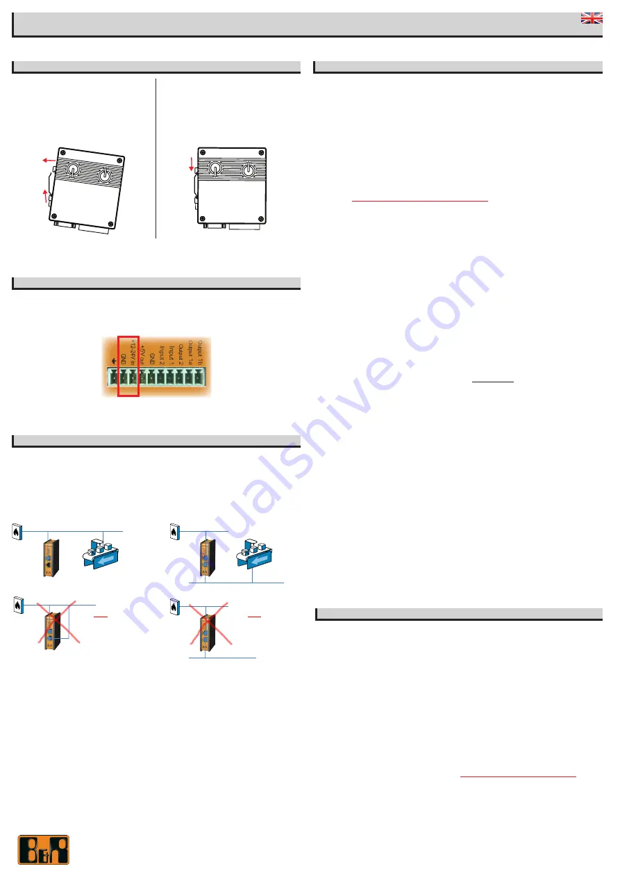
B
POWER
SiteManager must be fed 12 - 24V DC. Power consumption is max. 3W.
Power should be applied to the GND and +V terminals only!
It is recommended to connect the earth ground in order to reduce interference of noise.
C
Ethernet ports (DEV1 and UPLINK1)
Use a standard Ethernet patch cable (straight or cross over) to connect the
UPLINK1
port to a
switch in a network that has access to the Internet.
The DEV port can be connected to an existing network separate from the UPLINK1 network, or
you can create a separate device network isolated from the UPLINK1 network. But you can also
just connect the UPLINK1 port, and only access equipment on the Uplink side.
D
Applying UPLINK settings for accessing the Internet
The SiteManager requires being able to access the Internet via an
Uplink port
in order to
target a GateManager server. By default it will receive its IP address by DHCP, and you only
need to manually configure the Uplink settings if you will use a fixed IP on the Ethernet port
(UPLINK1), or if your SiteManager has a wireless option (UPLINK2) you may have to additionally
configure WiFi settings (model 1145) or broadband settings (model 1135).
Select one of the following 4 methods:
1.
Using
Automation Studio.
The feature will be available from firmware release 6.0, Q2 2015
2.
Using the
Appliance Launcher.
a.
Download and install the Appliance Launcher tool from here:
www.br-automation.com/appliance-launcher
b.
Connect the
DEV1
or
UPLINK1
port of the SiteManager to the local network and
power it on. The SiteManager must be on the same Subnet as your PC. Alterna-
tively connect the SiteManager with an Ethernet cable directly to your PC.
c.
Power on the SiteManager and wait approx. 1 minute for it to become ready.
d.
Start the Appliance Launcher and the SiteManager should be listed in the first
screen. If it does not appear immediately, try pressing the
Search
button a couple
of times. (Note that the Appliance Launcher will only show the SiteManager if your
PC has a genuine private IP address (10.x.x.x, 172.16-31.x.x, 192.168.x.x or 169.254.x.x))
e.
Follow the Wizard and set the
UPLINK1
address if you want to use a fixed IP ad-
dress, or continue the wizard to menu
UPLINK2
to set the
SSID/password
for the
integrated WiFi module (model 1145 only), or
PIN Code
for the integrated broadband
module (model 1135 only).
3.
Using the
default IP address
(10.0.0.1)
a.
Connect the DEV port of the SiteManager to the Ethernet port of your PC using a
standard Ethernet cable.
b.
Configure your PC’s Ethernet adapter to 10.0.0.2 subnet mask 255.255.255.0.
c.
Power on the SiteManager and wait approx. 1 minute for it to become ready.
d.
Type the following in your web browser: https://10.0.0.1
e.
Login with user
admin
and the SiteManagers’ MAC address as password (printed
on the product label).
f.
Enter menu
System
>
UPLINK1
to set the
UPLINK1
address if you want to use a
fixed IP address, or enter the menu
UPLINK2
to set the
SSID/WiFi Key
for the
integrated WiFi module (model 1145 only), or
PIN Code
for the integrated broadband
module (model 1135 only).
g.
Continue with section E to configure GateManager settings.
4.
Using a
DHCP server
a.
Connect the
UPLINK
port of the SiteManager to your local network and power it on.
b.
After approx. 1 minute the SiteManager should have received an IP address from
your DHCP server.
c.
Check the lease list of the DHCP server to see what the IP address is.
d.
Type the IP address in your web browser preceded with https:// (e.g.
https://192.168.41.13).
e.
Login with user
admin
and the SiteManagers’ MAC address as password (printed
on the product label).
f.
Enter menu
System
>
UPLINK1
to set the
UPLINK1
address if you want to set
a fixed IP address, or enter menu
UPLINK2
to set the
SSID/WiFi Key
for the
integrated WiFi module (model 1145 only), or
PIN Code
for the integrated broadband
module (model 1135 only).
g.
Continue with section E to configure GateManager settings.
E
Applying settings for connecting to a GateManager server
1.
In the SiteManager Web GUI enter the menu
GateManager
-->
General
(if using the Appli-
ance Launcher, follow the wizard to the
GateManager Parameters
page).
2. Enter the
IP address of the GateManager
server that the SiteManager should connect
to, and a
Domain Token
for the domain where the SiteManager should appear. You should
have received this information from your administrator or from where you received the
SiteManager.
3.
When the settings are entered, you should reboot the SiteManager. Observe that the
Status LED goes steady Green, which indicates that the SiteManager is connected to the
GateManager.
4.
Once attached to the GateManager, you can use the GateManager Console or a Link-
Manager Client to get remote access to the SiteManager Web GUI to perform additional
configuration (DEV ports, Agents etc.)
5. Detailed guides, can be found on this page:
www.br-automation.com/sitemanager
SITEMANAGER 1115/1135/1145
INITIAL SETUP
Ber Rainer Industrie-Elektronik Gesellschaft m.b.H.,
FN 111651 v, B&R-Straße 1, 5142 Eggelsberg, Österreich
DOC: SM1115-1135-1145_initial_contact_v06
DO
NOT
CONNECT THE
DEV
AND
UPLINK1
PORTS TO THE SAME
PHYSICAL NETWORK
192.168.2.100/24
192.168.2.2/24
IP 10.0.0.2
192.168.2.2/24
192.168.2.5/24
DO
NOT
ASSIGN
DEV
ADDRESS IN THE SAME
LOGICAL NETWORK AS
UPLINK1


