B&G V90S, User Manual
The B&G V90S Quick Start Manual offers essential guidance to maximize the functionality of your device. Ensure seamless usage by downloading the manual for free from manualshive.com. This user-friendly guide provides all the key instructions and troubleshooting tips needed to enjoy the full capabilities of the V90S.
Share
Download


Reviews:
No comments
Related manuals for V90S
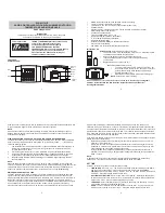
WS-8117U-IT
Brand: La Crosse Technology Pages: 3

Tone
Brand: i-box Pages: 18

00054896
Brand: Hama Pages: 18

MKIII UNIT 3
Brand: Harken Pages: 78

CR-114IPH
Brand: Technika Pages: 24

BP9
Brand: Blaupunkt Pages: 28

SPK-QC001
Brand: Laser Pages: 8

rescureME MOB1
Brand: Ocean Signal Pages: 4

TRX-05W1
Brand: TRX Pages: 28

IP507
Brand: prologue Pages: 40

CC Skywave SSB
Brand: C. Crane Pages: 32

350 A
Brand: ZF Pages: 56

SR 562
Brand: Kongsberg Pages: 41

ld7
Brand: Veripos Pages: 62

0000/3929
Brand: TechniSat Pages: 68

DIGITRADIO 370 CD IR
Brand: TechniSat Pages: 172

0000/3955
Brand: TechniSat Pages: 196

Cobra 25 NW ST
Brand: Cobra Pages: 20


