background image

Hydra 2000 User Manual

HB-0844-02

USER MANUAL

Premier Way, Abbey Park

Romsey, Hampshire, S051 9AQ

England

Tel: (+44) 01794 518448

Fax: (+44) 01794 518077

www.bandguk.com

Summary of Contents for Hydra 2000

Page 1: ...Hydra 2000 User Manual HB 0844 02 USER MANUAL Premier Way Abbey Park Romsey Hampshire S051 9AQ England Tel 44 01794 518448 Fax 44 01794 518077 www bandguk com...

Page 2: ...ANUAL CONTENTS Product Liability and Safety Warnings Record of Amendments PART 1 INTRODUCTION PART 2 OPERATING INFORMATION PART 3 CALIBRATION PART 4 INSTALLATION INFORMATION PART 5 OPTIONS PART 6 DIAG...

Page 3: ...e safe operation of this equipment is dependent on accurate and correct calibration Incorrect calibration of this equipment may lead to false and inaccurate navigational readings placing the yacht int...

Page 4: ...Hydra 2000 User Manual HB 0844 02 RECORD OF AMENDMENTS Date Amendment Number Description Signature...

Page 5: ...5 1 3 5 Super Halcyon 3 Fluxgate Compass 1 5 1 3 6 Halcyon 2000 Compass 1 5 1 3 7 Additional Sensors 1 5 1 4 DISPLAYS 1 5 1 4 1 NMEA Full Function Display FFD 1 5 1 4 2 Standard FFD 1 6 1 4 3 20 20 D...

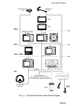
Page 6: ...2000 Main Processor Sonic Speed Unit Network Boat Speed NMEA FFD Chart Table Deck Mast Hull Halcyon GPS Antenna Unit GPS Plus Depth 000 EP 000 000 Halcyon 2000 Compass Additional Sensors Sea and Air T...

Page 7: ...and true wind direction etc These functions are controlled from a Full Function Display FFD A typical system is shown in Figure 1 1 Typical Hydra 2000 System Block Diagram 1 2 PROCESSORS 1 2 1 Main P...

Page 8: ...urther details are given in Part 5 Options 1 3 SENSORS 1 3 1 Masthead Unit The Masthead Unit senses apparent wind speed and wind angle The unit is light weight and sealed 1 3 2 Paddle Wheel The Paddle...

Page 9: ...00 instrument systems through the B G Fastnet Network The Halcyon 2000 Compass has the ability to learn the magnetic effect of the vessel on the compass and automatically apply deviation correction 1...

Page 10: ...roduced a number of standard specifications for the interconnection of marine electronic instruments These standards specify the electrical signals and the format of the data to be transferred Part 2...

Page 11: ...the damping on most functions is adjustable This allows you to slow down the response of the function if it is too jumpy in rough weather and similarly to speed it up if it is too slow in flat water T...

Page 12: ...lect until you find the one you want Having found the correct menu entry it is then selected the FFD then displays the first choice in the next level of menu down Here you once again scroll through th...

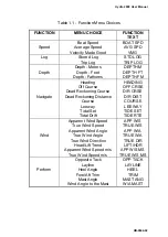
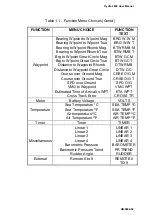
Page 13: ...ad Reckoning Course Dead Reckoning Distance Course Leeway Tidal Set Tidal Drift HEADING OFF CRSE D R CRSE D R DIST COURSE LEEWAY TIDE SET TIDE RTE Wind Apparent Wind Speed True Wind Speed Apparent Win...

Page 14: ...und True SPD over Ground VMG to Waypoint Estimated Time of Arrival to WPT Cross Track Error BRG W W M BRG W W T BTW RMB M BTW RMB T BTW GC M BTW GC T DTW RMB DTW GC CRSE O G M CRSE O G T SPD O G VMG W...

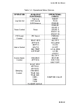
Page 15: ...Control Timer FREEZE START 0 START 5 START 10 START 15 PR Trend Control PR Trend PERIOD RESET Alarm Control BOAT SPD APP W S DEPTH VOLTS SEA TEMP AIR TEMP ALL OFF HI ALARM HI ON HI OFF LO ALARM LO ON...

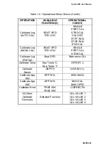
Page 16: ...RUN END CAL Calibrate Log MANL CAL BOAT SPD STD LOG SINGLE PORT CAL STDB CAL Calibrate Log Ref Cal Boat SPD Reference CAL Calibrate Temp Sea Temp C Sea Temp F OFFSET C Calibrate Datum DEPTH DATUM Cali...

Page 17: ...2 2 20 20 DISPLAY 2 8 2 3 SUPER HALCYON 3 AND HALCYON 2000 COMPASS 2 8 2 4 HALCYON DISPLAY 2 9 2 5 EXAMPLES OF OPERATION 2 9 2 5 1 Function Selection 2 9 2 5 2 Page Display Configuration 2 10 2 5 3 N...

Page 18: ...metric Pressure Trend 2 22 2 11 7 Battery Voltage 2 23 2 11 8 Bearing to Waypoint 2 23 2 11 9 Bearing Waypoint to Waypoint 2 23 2 11 10 Boat Speed 2 24 2 11 11 Course 2 24 2 11 12 Course Over Ground 2...

Page 19: ...35 2 11 34 Time to Layline 2 36 2 11 35 Time to Waypoint 2 36 2 11 36 Trip Log 2 36 2 11 37 True Wind Angle 2 37 2 11 38 True Wind Direction 2 38 2 11 39 True Wind Speed 2 39 2 11 40 Velocity Made Goo...

Page 20: ...each FFD consists of a page of information comprising an upper display and a lower display The FFD has four pages available that may be configured to display any function available in either the uppe...

Page 21: ...ges from full brightness to OFF The next press gives full illumination again This operation on any one FFD within the system performs the same sequence on all Hydra displays connected to the system Ho...

Page 22: ...o increase or decrease numerical values such as calibration values Immediately after a specific page has been selected pressing the Scroll Up Key will select the upper display Similarly operation of t...

Page 23: ...unctions Successive operation of the SPD DEP Key will display the following information in a fixed order Boat Speed Depth Boat Speed Speed Over Ground from NMEA Position Fix Boat Speed Apparent Wind A...

Page 24: ...ll change the display to show RESET flashing or if TIMER is selected START 10 flashing Pressing the Remote Button again will Reset that function or in the case of TIMER start the countdown After a res...

Page 25: ...OPERATION The general principle of operating the Hydra 2000 will be made clear by the following examples of Function Page Selection and Damping 2 5 1 Function Selection Our first example will be to se...

Page 26: ...ermanent new page proceed as follows 1 Press Scroll Up or Scroll Down and scroll text until CNFG DSP is shown on Display Note Scroll Up or Scroll Down can be used because we are configuring the whole...

Page 27: ...n refer to OPERATING Menu choices Table 1 2 1 Using the Scroll Up or Scroll Down Key select the upper or lower display as required 2 If BOAT SPD is in the upper display press and hold Scroll Down and...

Page 28: ...ower display use Scroll Up 3 Press Enter and then press Scroll Down to select MANL CAL on the Display 4 Press Enter and SINGLE is shown on the Display Notes 1 SINGLE is the choice required if a single...

Page 29: ...l Down Keys to set the new DATUM value Note If DATUM is referenced to the water line the value is positive If DATUM is referenced to the keel line the value is negative and this is indicated by a minu...

Page 30: ...ormal The audible alarm if fitted is also silenced by this operation After this the lower display continues to monitor the alarm condition The alarm is still active and if the alarm parameter is again...

Page 31: ...on is in the upper display press Scroll Down and scroll the lower display until ALARMS appears flashing If the selected function is in the lower display use Scroll Up 3 Press Enter and the text shows...

Page 32: ...F and the normal page display will be restored WARNING All alarms in the system will remain OFF until the values are reset or the individual alarms are switched ON again 2 8 TRIP FUNCTIONS The Hydra 2...

Page 33: ...s Trip Log Timer and Barometric Pressure Trend Fast Reset can be initiated either by operation of a Remote Push Button see Para 2 1 9 or by operation of the Enter Key on any FFD Note If two trip funct...

Page 34: ...lashing 3 Press Enter and use the Scroll Down key to display RESET flashing 4 Press the Enter key and the display now shows RUN flashing 5 Press the Enter key again and the display shows the trip log...

Page 35: ...play up on deck 2 9 2 Select System Control 1 Press and hold Scroll Up or Scroll Down until LIGHTING is displayed in the text 2 Press Enter and Scroll Up or Scroll Down to select SYSTEM 3 Press Enter...

Page 36: ...NCTIONS The previous Paragraphs have described how the Hydra System is built up and how to use the keys and basic menu structure The following Paragraphs describe each of the functions available in mo...

Page 37: ...11 3 Apparent Wind Speed Menu Heading WIND Function Text APP W S Update Rate Twice per second Units Knots or metres per second Notes 1 Variable damping 0 99 seconds 2 Audible high low alarm available...

Page 38: ...alibration CAL VAL1 of the pressure sensor is checked against an accurate barometer and adjusted accordingly To select CAL VAL1 for calibration proceed as follows MISC BAROMETER CALBRATE CAL VAL1 2 11...

Page 39: ...tmeter measure the voltage then enter this actual voltage in using the following sequence MOTOR VOLTS CALBRATE CAL VAL1 2 11 8 Bearing to Waypoint Menu Heading WAYPOINT Function Text BTW RMB or BTW GC...

Page 40: ...igher functions e g true wind angle speed direction VMG the log and trip functions The accurate calibration of the paddlewheel or sonic speed sensor is essential Hydra uses simple procedures for calib...

Page 41: ...is your actual track over ground and is invaluable to the navigator for dealing with tidal areas 2 11 13 Dead Reckoning Menu Heading NAVIGATE Function Text D R CRSE or D R DIST Update Rate Once per s...

Page 42: ...2 2 26 In the worst case a Man Overboard MOB situation immediately resetting the Dead Reckoning DR will bring the vessel back to the MOB position DR is the course over the water and not over the land...

Page 43: ...ea state sea bed conditions air and plankton in the water But however good the equipment there will always be times when a reliable measurement of depth is not possible In these cases such as followin...

Page 44: ...g NAVIGATE Function Text HEADING Update Rate Twice per second Units Degrees magnetic Notes 1 Adjustable damping 0 99 sec 2 Sector alarm available 3 Sensor alignment calibration 4 Moving card analogue...

Page 45: ...Trend Menu Heading WIND Function Text LIFT HDR Update Rate Once per second Units Degrees Notes 1 Requires Halcyon Display 2 Analogue indicator available This function is particularly useful to racing...

Page 46: ...For the Hydra to be able to measure this it needs to know the heel angle and hence a clinometer must be fitted Leeway is of great importance in the calculation of Dead Reckoning since leeway can consi...

Page 47: ...the Enter Key once A further press of the Enter Key returns the display to hours and minutes 2 11 24 Mast Angle Menu Heading PERFORM Function Text MAST ANG Update Rate Once per second Units Degrees No...

Page 48: ...lay is connected to the system The amount off course is indicated on the Halcyon bar graph and shown numerically on other Hydra displays A dedicated analogue indicator is also available For further in...

Page 49: ...MP Update Rate Once per second Units Degrees Centigrade Fahrenheit Notes 1 Requires temperature sensor 2 Audible high low alarm available Useful on long distance sailing when ocean currents are discer...

Page 50: ...resettable the trip log is used for this purpose Normally the Log function displays nautical miles to two decimal places i e 99 99nm maximum One press of the Enter Key expands the display to 0099nm g...

Page 51: ...ortant In rapidly changing tidal situations you need to lower the damping right down to be able to see changes quickly Conversely in a steady tide or current the longer time the calculation is average...

Page 52: ...ation displayed shows the time to go before reaching the appropriate layline A value of zero indicates time to tack or gybe 2 11 35 Time to Waypoint Menu Heading WAYPOINT Function Text TTG WPT Update...

Page 53: ...99 nautical miles by pressing the Enter Key 2 11 37 True Wind Angle Menu Heading WIND Function Text TRUE W A Update Rate Once per second Units Degrees Notes 1 Relative to the boat s heading 2 Correcte...

Page 54: ...ted for masthead and other errors via a Look Up Table see Part 3 Calibration 3 Damping control via true wind speed This is the tactician s greatest ally in the search for the right wind shifts It show...

Page 55: ...11 40 Velocity Made Good VMG Menu Heading SPEED Function Text VMG Update Rate Once per second Units Knots Note Upwind and Downwind Velocity Made Good VMG is calculated from the true wind angle and the...

Page 56: ...r than the helmsman This person should develop a feel for the Boat Speed when the greatest VMG is attained and then communicate these to the helmsman Fig 2 5 Calculation of VMG 2 11 41 Wind Angle to t...

Page 57: ...peed Angle Calibration 3 9 3 3 2 Apparent Wind Angle Calibration AWA 3 10 3 3 3 Apparent Wind Speed Calibration 3 11 3 4 COMPASS CALIBRATION 3 12 3 4 1 Principles of Compass Calibration Super Halcyon...

Page 58: ...ration Runs 3 5 3 2 Masthead Unit Alignment 3 10 3 3 Leeway Angle Measurement 3 17 3 4 True Wind Direction 3 18 3 5 Upwash 3 19 3 6 True Wind Direction Error 3 20 3 7 Depth Datum 3 22 TABLES Table No...

Page 59: ...al removes some of the mystique and breaks the calibration process down into a series of simple instructions These instructions when carefully undertaken in the right order will consistently produce g...

Page 60: ...ydra 2000 will always use the calibration value for the leeward paddle wheel sensor using the heel angle if it is fitted or the Apparent Wind Angle if it is not 3 2 2 Preparation for Log Calibration B...

Page 61: ...n as ascertained from the chart Fig 3 1 Log Calibration Runs The user is required to enter the distance X in nautical miles CAL DIST and then as the yacht passes marks A and B on each run to instruct...

Page 62: ...select the appropriate measured distance Press Enter to accept new distance The system is now ready to start the first calibration run 7 Press Scroll Down STRT RUN appears flashing 8 When crossing the...

Page 63: ...a Depth Unit is used in conjunction with the Hydra 2000 FFD Display version later than 5C To calibrate the Boat Speed by reference to a known value e g another boat with an accurately calibrated log p...

Page 64: ...the lower text now shows CAL VAL 1 flashing 7 Press Scroll Down repeatedly and the lower text will cycle through CAL VAL 1 CAL VAL 2 and CAL VAL 3 When CAL VAL 1 is displayed 8 Press Enter and the low...

Page 65: ...speed on one tack than the other then there is shear A good look at the general weather conditions is also helpful Do not calibrate in building sea breezes What of wind gradient then Well this is the...

Page 66: ...ve an error For example if the Apparent Wind Angle reads 4 then you should enter 4 as the calibration value If it is less than 0 then the opposite applies The second method involves a sailing trial as...

Page 67: ...re less on port than on starboard tack the value to be entered should be negative as denoted by the minus sign in the left of the calibration value The calibration value is entered into the system via...

Page 68: ...a degree per second during the 540 turn Super Halcyon 3 i e the 540 turn must not take longer than 45 minutes d The rate of change in heading is constant e Automatic calibration has been utilised by c...

Page 69: ...6 Type PLC Pilot 17 Type ACP Pilot 18 NMEA Heading NMEA FFD 96 Enter the required heading node by following the procedure below a Press the Scroll Up key until NAVIGATE is shown in the text flashing b...

Page 70: ...onditions for the calibration 3 Check for any large steel structures nearby that may cause additional erratic deviations 4 At a speed of about three knots slowly motor the boat through a full one and...

Page 71: ...with little traffic so you will not have to take avoiding action that would ruin the calibration The flatter the water and the less the wind the easier it will be to meet the conditions for calibratio...

Page 72: ...known it can be eliminated by entering the value into the Hydra under NAVIGATE HEADING CALBRATE CAL VAL1 For example the compass was reading 320 degrees and it should read 316 then the value to enter...

Page 73: ...is difficult and it may be more accurate to consult the designer for the vessel s theoretical figure In the absence of a figure a calculation of Leeway Coefficient can be made using the following for...

Page 74: ...e the leeway coefficient K is known it is entered into the system under NAVIGATE LEEWAY CALBRATE CAL VAL1 3 6 TRUE WIND CORRECTION It is finally time to go sailing and begin the calibration of the Tru...

Page 75: ...head Unit It is easy to see the true wind direction tack as little as 2 3 degrees which would mean the correction factors being as accurate as 0 5 or about 1 The Hydra 2000 has a simple easy to use me...

Page 76: ...on is calculated empirically and from which some general rules can be determined Fig 3 6 True Wind Direction Error Fig 3 6 is a typical situation sailing on a port tack upwind in a ten knot wind the t...

Page 77: ...the required number of degrees correction i e 5 Use the Scroll Up and Scroll Down Keys to increase or decrease the value accordingly Pressing the Enter Key sets this figure in the Hydra 2000 memory A...

Page 78: ...2 Wind Angle True Wind Speed 5 10 15 20 25 30 Downwind 180 0 0 5 1 0 1 5 2 0 2 5 Table 3 2 Example of True Wind Speed Correction Table The corrections are found in the menu under WIND TRUE W S CALBRA...

Page 79: ...he Computer Unit connection block CAL VAL1 is altered to match the value from the voltmeter 3 9 SEA TEMPERATURE CALIBRATION If a suitable temperature sensor is fitted the Hydra 2000 will monitor the c...

Page 80: ...2 flashing 5 Press Enter the lower text now shows OFFSET C 6 Press Enter the lower text now shows OFFSET C flashing and by use of Scroll Up Down the temperature should be changed to the reference valu...

Page 81: ...Hydra 2000 User Manual Part 4 Installation Information HB 0844 02 4 1 PART 4 INSTALLATION INFORMATION CONTENTS Para Page 4 1 INTRODUCTION 4 2 4 2 INSTALLATION DATA SHEETS 4 3...

Page 82: ...ation data sheets are details of cables cable colours instructions for installation and notes to assist the technician The installation sheets following are 1 Sonic Speed Unit and Sonic Transducers 2...

Page 83: ...Hydra 2000 User Manual Part 4 Installation Information HB 0844 02 4 3 4 2 INSTALLATION DATA SHEETS...

Page 84: ...Hydra 2000 User Manual Part 4 Installation Information HB 0844 02 4 4...

Page 85: ...Hydra 2000 User Manual Part 4 Installation Information HB 0844 02 4 5...

Page 86: ...Hydra 2000 User Manual Part 4 Installation Information HB 0844 02 4 6...

Page 87: ...Hydra 2000 User Manual Part 4 Installation Information HB 0844 02 4 7...

Page 88: ...Hydra 2000 User Manual Part 4 Installation Information HB 0844 02 4 8...

Page 89: ...Hydra 2000 User Manual Part 4 Installation Information HB 0844 02 4 9...

Page 90: ...Hydra 2000 User Manual Part 4 Installation Information HB 0844 02 4 10...

Page 91: ...Hydra 2000 User Manual Part 4 Installation Information HB 0844 02 4 11...

Page 92: ...Hydra 2000 User Manual Part 4 Installation Information HB 0844 02 4 12...

Page 93: ...Hydra 2000 User Manual Part 4 Installation Information HB 0844 02 4 13...

Page 94: ...Hydra 2000 User Manual Part 4 Installation Information HB 0844 02 4 14...

Page 95: ...Hydra 2000 User Manual Part 4 Installation Information HB 0844 02 4 15...

Page 96: ...ected in accordance with these instructions NMEA cable shields must be connected at the TRANSMITTING end The NMEA output cable shield should be connected to the other cable shields in the junction box...

Page 97: ...An FFD can be connected at any point on the system network Multiple FFD s can be used on the system network Each can control and enter data into the system processor memory FFD s can be used in combi...

Page 98: ...tion 5 4 5 3 ANALOGUE INDICATORS 5 5 5 3 1 Options Available 5 5 5 3 2 Analogue Indicator Configuration 5 6 5 3 3 Meter Scaling 5 7 5 4 GRAVITY SWITCH 5 7 5 5 AUDIBLE ALARM 5 7 5 6 20 20 DISPLAY 5 8 5...

Page 99: ...ift Trend 20 20 Display 5 15 5 8 10 Turn Rate Function 5 15 5 9 EXPANSION PROCESSOR 5 16 5 9 1 The Expansion Processor 5 16 5 9 2 Linear Function Settings 5 16 5 9 3 Calibrating a Linear Channel 5 17...

Page 100: ...of the boat s trim using a clinometer 5 2 2 Mast Rotation Sensor This is essential if your mast rotates otherwise you lose all the wind angle functions The addition of this unit gives two new functio...

Page 101: ...input that B G have anticipated then you need take no action beyond the connection itself since the default linear input configuration will be the right one The default settings for the four inputs o...

Page 102: ...n 215 HL 016 Magnified Wind Direction 40 0 40 degrees 215 HL 017 Head Lift Trend 40 0 40 degrees 215 HL 152 Depth 0 to 200 metres 215 HL 025 Depth 0 to 100 Ft fathoms 215 HL 026 Compass Card 360 215 H...

Page 103: ...ation sheet to determine the meter options and their respective meter drives 4 With the appropriate meter output flashing in the top display press Enter to reveal the current option assigned to that m...

Page 104: ...To change this e g to 25 knots press Enter and then Scroll Up to increase the number to 25 0 A final press of Enter will then enter the new maximum scale The Boat Speed Meter will read between 0 and...

Page 105: ...however provided with 14 pre set functions which may be selected by use of a Remote Button connected to the display or via any FFD on the system The pre set functions are as follows Boat Speed Depth...

Page 106: ...of the standard FFDs on the system Any 20 20 can be controlled from any FFD To change the function displayed on a 20 20 using a standard FFD proceed as follows 1 At the FFD press and hold down the Pag...

Page 107: ...select the function you wish to change 4 Press the Enter Key and the function currently being displayed on the 20 20 will start to flash 5 Press and hold down the Scroll Up Key and cycle through the...

Page 108: ...ether with a bar graph indicating port and starboard off course error relative to a set course The display area is split into three The three large digits in the upper left part always show compass he...

Page 109: ...st in steering a steady and accurate course Off Course is calculated by comparing the yacht s current heading with a previously set reference heading The deviation is shown by the bar graph and numeri...

Page 110: ...Stored Course Function 2 Press Scroll Up and CRS 1 will flash 3 Using the Scroll Up and or Scroll Down Keys select the course CRS number required 4 Press the Enter Key to enter the selected course as...

Page 111: ...g the reference at the start of the leg will then give the head and lift trends from that point onwards 5 8 7 Set up Port and Starboard References In this application the Halcyon Display will always k...

Page 112: ...is selected by pressing the Enter Key the display defaults to Mean Rate of Turn and MEAN is shown on the display When MEAN is selected the present heading is compared with a continually updated mean h...

Page 113: ...a load cell giving a linear change in voltage as the load increases may be connected to a linear input LINEAR 5 has four calibration values other linear functions have three calibration values found...

Page 114: ...output is 0V MIN VAL 000 and if maximum load is 650 kgF at 6 5V then MAX VAL 650 Calibration value 4 is only available on Linear 5 and this displays a value between 05 and 16 This setting determines t...

Page 115: ...OS Violet 7 Meter 8 SIN Green 8 Meter 8 COS Blue 9 Meter Lighting Yellow 10 Meter Common Orange 11 Meter Ground Black 12 N C 13 N C 14 Network Data ve Green 15 Network Data ve White 16 Network Screen...

Page 116: ...35 N C 36 N C 37 Linear 10 Input Green 38 N C 39 Linear 11 Input Green 40 Linear 12 Input Green 41 12V Switched Supply Red 42 Linear 13 Input Green 43 6 5V Sensor Supply Red 44 RPM Input Green 45 Gro...

Page 117: ...sthead Unit 6 7 6 3 DEPTH SOUNDER 6 8 6 3 1 Yacht Stationary 6 8 6 3 2 Yacht Moving 6 9 6 3 3 Consistently Shows Shallow Depth 6 10 6 3 4 Random Deep Depths 6 11 6 4 ERROR MESSAGES 6 12 6 4 1 Error Me...

Page 118: ...ched on as follows 1 Power up the system by simultaneously pressing the Power Lights and Enter Keys until DIAGNOST appears on the upper text in an otherwise blank display 2 Press Enter and the first t...

Page 119: ...characters blanks the display and turns on all segments When all segments are turned on 16 characters are displayed at the top and bottom of the display In the rest of the test and in normal operation...

Page 120: ...when power is switched OFF If this fails FATAL ER 03 or FATAL ER 04 will be displayed The display s page configuration and possibly the text for some functions will be lost 6 1 8 Lighting This test ch...

Page 121: ...number 6 1 12 Errors This test is used chiefly to interrogate the Hydra 2000 network and is designed mainly for use by service technicians to ascertain levels of interference that may be present For...

Page 122: ...with wind speed or wind angle first check the cable connections at the main processor and at the mast base junction box The easiest way to test the MHU cable is by substituting a spare cable If the ca...

Page 123: ...a FFD 6 3 1 Yacht Stationary Symptom Display consistently shows Floating Bars when well within the range of the sounder with the yacht stationary in the water This is an indication that no consistent...

Page 124: ...oving This is most often an indication of difficult sounding conditions but can also indicate a badly positioned transducer Possible Causes a Difficult sounding conditions and or depth sounder unable...

Page 125: ...sider fitting two transducers with a changeover switch 6 3 3 Consistently Shows Shallow Depth Symptom Display consistently shows a shallow depth between 0 and about 1 5m Possible causes a Faulty trans...

Page 126: ...ly suppressed The depth sounder measures the ambient noise and this can be found for display by looking under the PARAMTR Menu When the boat is stationary electrical equipment should be switched ON an...

Page 127: ...ide their normal range Try disconnecting the sensors in turn Er02 Error detected when writing to the analogue to digital converter on the depth sounder board This can indicate the same problems as Er0...

Page 128: ...e result is always FAIL There is a source of magnetic deviation near to the Halcyon 2000 compass Try re positioning the compass and perform the calibration 6 5 2 Heading Shows Err Possible Cause The s...

Page 129: ...heading source Pilot Heading Node must be set to Node 16 If the Halcyon 2000 is not to be the source of heading then it must be unplugged from the network 6 5 5 True Wind Direction Tide Set or DR Cou...

Page 130: ...HSC 3 Heading steering HVD Magnetic variation automatic HVM Magnetic variation manually set MTA Air Temperature Centigrade MTW Water Temperature Centigrade RMA Recommended min implementation sentence...

Page 131: ...Velocity MWV Wind Speed and Angle VHW Heading and Water Speed VLW Log mileage Water referenced VPW Velocity parallel to true wind device measured VTG Actual Track and Ground Speed VWR Wind Relative B...

Page 132: ...Hydra 2000 User Manual Part 6 Diagnostic Data HB 0844 02 6 16 NMEA Sentences The following diagrams show the structure of the various NMEA sentences 1 Autopilot format A APA 2 Autopilot format B APB...

Page 133: ...Hydra 2000 User Manual Part 6 Diagnostic Data HB 0844 02 6 17 3 Bearing and distance to waypoint great circle dead reckoned BEC 4 Bearing and distance to waypoint rhumb dead reckoned BER...

Page 134: ...Hydra 2000 User Manual Part 6 Diagnostic Data HB 0844 02 6 18 5 Bearing to destination waypoint from origin waypoint true or magnetic BOD 6 Bearing and distance to waypoint great circle measured BWC...

Page 135: ...Hydra 2000 User Manual Part 6 Diagnostic Data HB 0844 02 6 19 7 Bearing and distance to waypoint rhumb line measured BWR 8 Bearing to waypoint from waypoint true and magnetic BWW...

Page 136: ...Hydra 2000 User Manual Part 6 Diagnostic Data HB 0844 02 6 20 9 Depth of water below transducer DBT 10 Global positioning fix data GGA...

Page 137: ...Hydra 2000 User Manual Part 6 Diagnostic Data HB 0844 02 6 21 11 Present fix position GLL 12 Present position fix Loran C GLP...

Page 138: ...Hydra 2000 User Manual Part 6 Diagnostic Data HB 0844 02 6 22 13 Present heading magnetic HDM 14 Heading degrees true HDT 15 Air temperature Celsius MTA 16 Water temperature MTW...

Page 139: ...Hydra 2000 User Manual Part 6 Diagnostic Data HB 0844 02 6 23 17 Surface wind direction and velocity MWD 18 Wind speed and angle MWV...

Page 140: ...Hydra 2000 User Manual Part 6 Diagnostic Data HB 0844 02 6 24 19 Recommended minimum implementation sentence Loran C RMA 20 Recommended minimum implementation sentence navigation information RMB...

Page 141: ...a 2000 User Manual Part 6 Diagnostic Data HB 0844 02 6 25 21 Recommended minimum implementation sentence GPS or transit specific GPS RMC 22 Water speed and heading VHW 23 Water referenced log mileage...

Page 142: ...Hydra 2000 User Manual Part 6 Diagnostic Data HB 0844 02 6 26 24 Device measured velocity parallel true wind VPW 25 Actual track and ground speed VTG 26 Wind relative bearing and velocity VWR...

Page 143: ...Hydra 2000 User Manual Part 6 Diagnostic Data HB 0844 02 6 27 27 True wind relative bearing and velocity VWT 28 Waypoint closure velocity WCV 29 Distance to waypoint great circle WDC...

Page 144: ...Hydra 2000 User Manual Part 6 Diagnostic Data HB 0844 02 6 28 30 Distance to waypoint Rhumb WDR 31 Measured cross track error XTE 32 Dead reckoned cross track error XTR...

Page 145: ...Hydra 2000 User Manual Part 6 Diagnostic Data HB 0844 02 6 29 33 Time and distance to layline ZDL 34 Time of day ZLZ 35 Time to waypoint ZTG...

Page 146: ...tion at 180 A1 2 True Wind Angle Correction Table Wind Angle True Wind Speed 5 10 15 20 25 30 Upwind Reaching Downwind A1 3 Hydra 2000 Settings Table Function Calibration Type Unit Calibration Value D...

Page 147: ...Value Alarm Alarm Value DEPTH Datum Offset High m ft or fms Low HEADING Alignment Sector HEEL Alignment LEEWAY Alignment MAST ANG Alignment RUDDER Alignment SEA TEMP Sensor Type High Offset Temp C or...

Reviews: