background image


OPERATOR’S MANUAL 


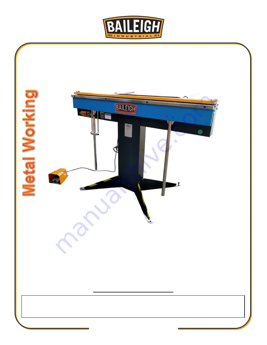
MAGNETIC BOX AND PAN BRAKE 

MODEL: BB-4816M-V2 


Baileigh Industrial 

P.O. Box 531 

Manitowoc, WI 54221-0531 

Phone: 920.684.4990 

Fax: 920.684.3944 

[email protected] 


© 2022 Baileigh Industrial 

REPRODUCTION OF THIS MANUAL IN ANY FORM WITHOUT WRITTEN APPROVAL OF BAILEIGH INDUSTRIAL IS 
PROHIBITED. Baileigh Industrial, Inc. does not assume and hereby disclaims any liability for any damage or loss 
caused by an omission or error in this Operator’s Manual, resulting from accident, negligence, or other occurrence. 

Edition 2   03/2023 

Summary of Contents for BB-4816M-V2

Page 1: ...pwindustries com 2022 Baileigh Industrial REPRODUCTION OF THIS MANUAL IN ANY FORM WITHOUT WRITTEN APPROVAL OF BAILEIGH INDUSTRIAL IS PROHIBITED Baileigh Industrial Inc does not assume and hereby discl...

Page 2: ...ts 9 Transporting And Lifting 12 Installation 13 Anchoring The Machine 13 Overall Dimensions 14 Assembly And Set Up 15 Electrical 17 Operation 19 Magnetism Notes 21 Bending Allowance 22 Understanding...

Page 3: ...ce to Seller of any suspected defect in the Goods prior to the expiration of the warranty period The original end user must also obtain a RGA from Seller prior to returning any Goods to Seller for war...

Page 4: ...her remedies provided under this Agreement or at law or equity Attorney s Fees In the event legal action is necessary to recover monies due from Buyer or to enforce any provision of this Agreement Buy...

Page 5: ...Description of the functional parts of the machine Capacity charts Setup and start up instructions Machine operation Scheduled maintenance Parts lists GENERAL NOTES After receiving your equipment remo...

Page 6: ...zardous situation which if not avoided will result in death or serious injury WARNING Indicates a hazardous situation which if not avoided could result in death or serious injury CAUTION Indicates a h...

Page 7: ...d the counterweight They are heavy and can swing back suddenly causing serious body or head injuries ELECTRICAL AND MAGNETIC FIELDS Electric current and magnetic fields EMF These magnetic fields can h...

Page 8: ...making any modifications or alterations to a Baileigh machine Modifications or alterations to a machine may pose a substantial risk of injury to the operator or others and may do substantial damage to...

Page 9: ...machine when you are tired 14 Check for damaged parts Before using any tool or machine carefully check any part that appears damaged Check for alignment and binding of moving parts that may affect pro...

Page 10: ...support department can be reached at 920 684 4990 and asking for the support desk for purchased machines Tech Support handles questions on machine setup schematics warranty issues and individual parts...

Page 11: ...ge painted surfaces Follow manufacturer s label instructions when using any type of cleaning product After cleaning wipe unpainted metal surfaces with a light coating of quality oil or grease for prot...

Page 12: ...10 10 3 4 1 2...

Page 13: ...tch 1 3 Back Feet 2 4 Front Feet 2 5 Tool Tray 1 6 Back Stop Collars 2 7 Back Stop Bars 2 8a Notched Clamping Bar Long 1 8b Narrow Clamp Bar 1 8c Wide Clamp Bar Long 1 8d Segmented Clamp Bar Assortmen...

Page 14: ...o the floor Level the machine so that all the supporting feet are taking the weight of the machine and no rocking is taking place Follow these guidelines when lifting crane or hoist Always lift and ca...

Page 15: ...depends on the precise placement of it to the mounting surface FLOOR This tool distributes a large amount of weight over a small area Make certain that the floor is capable of supporting the weight o...

Page 16: ...14 14 OVERALL DIMENSIONS...

Page 17: ...position with a suitable lifting device Tool Tray and Back Gauge Supports 1 Attach the tool tray to the back of the brake using 3 M8x12 socket cap screws and 3 lock washers 2 Lay the rubber mat into t...

Page 18: ...a marker to mark the top surface of the extension bar 2 Remove and retain the mounting bolts A and remove the extension bar and store with the clamping bars 3 When installing the extension bar verify...

Page 19: ...cuit should be protected with a time delay fuse or circuit breaker with a amperage rating slightly higher than the full load current of machine A separate electrical circuit should be used for your to...

Page 20: ...tely Power cord connection 1 Verify that power is turned OFF on the control panel and the power source 2 Unwrap the power cord and route the cord away from the machine toward the power supply a Route...

Page 21: ...stalled 3 Set the machine for the material thickness you will be bending Raise the bending leaf 90 as shown in fig 7 Rotate the knobs on each end of the clamping bar which adjusts the setback distance...

Page 22: ...standing springback There is also a locking collar on the indicating shaft which can be set and locked to duplicate multiple bends 9 After the bend is made lower the bending leaf DO NOT ALLOW THE BEND...

Page 23: ...it may help to use an external fan to provide some air movement Magnetic materials such as the steel used for the clamping bars will become weakly magnetized by being in contact with strong magnets Ov...

Page 24: ...ession and stretch After the bending leaf is removed from the metal and the load is released the piece part relaxes forcing the bent portion of the metal to return slightly to its original shape The k...

Page 25: ...y secured bend the material as far as the bending leaf will allow Normal bending procedure 2 Now remove the clamping bar bring up the bending leaf and continue the fold as in fig 12 No clamping is req...

Page 26: ...ctromagnet and rotate the piece part down to the horizontal position 4 Continue the above procedure until you are satisfied with the result Making a Box with Clamping Bars 1 Using a long clamp bar ini...

Page 27: ...lifts automatically for easy insertion and removal of the piece part 1 Fold two opposite sides and the corner tabs with the slotted clamp bar The slots will NOT affect these bends 2 Select two slots...

Page 28: ...d components and sliding devices Apply rust inhibitive lubricant to all non painted surfaces Note Proper maintenance can increase the life expectancy of your machine WARNING Make sure the electrical d...

Page 29: ...can be checked periodically with a precision straight edge Checking the Gap 1 Raise the bending leaf up to a 90 position as shown in fig 20 2 Secure with the locking collar fig 21 on the leaf angle in...

Page 30: ...28 28 PARTS DIAGRAM...

Page 31: ...X30 4 13 BA1 208 Connect plate 1 14 GB T70 1 Screw M8X16 4 15 BA1 209 Cover 1 16 BA1 210 Right 1 17 BA1 211 Left Shield 1 18 GB T70 1 Screw M8X20 4 19 BA1 212 Spoke 1 20 BA1 213 Bending plate 1 21 BA1...

Page 32: ...26 Ball seat 3 41 GB T6170 Disc spring 6 2x12 5 1 42 GB T6170 Nut M6 2 43 BA1 227 Workbench 1 44 GB T70 1 Screw M8X12 3 45 GB T70 1 Screw M8X12 4 46 BA1 228 Back stop bar 2 47 BA1 229 Tray 1 48 BA1 23...

Page 33: ...CD4 Toggle Switch 1 7 BA1 170 KSD301 Temp Switch 1 8 BA1 171 RPF2BP7 Relay 1 9 BA1 172 2 2R 5W R1 Resistor 1 10 BA1 173 220R 10W R2 Resistor 1 11 BA1 174 6 8R 20W R3 Resistor 1 12 BA1 175 15UF 450V C1...

Page 34: ...rcuit breakers Have qualified electrician check circuit Return bending leaf to lower position and press start button Adjust bending leaf micro switch to be pressed in when leaf is in the released posi...

Page 35: ...need adjusting The actuator can be adjusted by loosening the screw that secures it making the adjustment followed by re tightening the screw If the micro switch does not click on and off after you ha...

Page 36: ...34 34 BAILEIGH INDUSTRIAL 1625 DUFEK DRIVE MANITOWOC WI 54220 PHONE 920 684 4990 FAX 920 684 3944 www baileigh com...

Reviews: